IMPORTANT DISCLAIMER: This guide references NFPA 92, Standard for Smoke Control Systems; NFPA 101, Life Safety Code; NFPA 204, Standard for Smoke and Heat Venting; NFPA 1, Fire Code; and the International Building Code (IBC). These codes vary significantly by edition and are frequently amended by state and local jurisdictions. NFPA 92 editions include 2012, 2015, 2018, 2021, and 2024. The most recent published edition is NFPA 92 (2024), but AHJ-adopted editions commonly lag behind by one or more cycles. NFPA 92A and NFPA 92B were merged into NFPA 92 in the 2012 edition — NFPA 92A covered smoke containment systems using barriers and pressure differences, while NFPA 92B covered smoke management systems in malls, atria, and large spaces. IBC section numbers and adopted NFPA editions vary by jurisdiction — verify against the code your AHJ enforces. Local amendments and the edition adopted by your Authority Having Jurisdiction (AHJ) always control. This guide is a starting point only—always verify the specific requirements applicable to your project with your local AHJ.
Smoke control systems are among the most complex and least understood fire protection systems. They do not extinguish fires or suppress flames. They manage the movement of smoke to maintain a tenable environment for occupant egress and firefighter operations.
A smoke control system can be as simple as a stairwell pressurization fan or as complex as a zoned smoke management system serving an interconnected atrium and multiple floors. It can use dedicated equipment or share components with the building HVAC system. And unlike sprinklers—which operate automatically on their own—smoke control systems depend on detection, control logic, and fans and dampers working together to function when needed.
This guide covers the fundamentals of smoke control system design and testing under NFPA 92, with a focus on system types, design approaches, and the acceptance and periodic testing that determine whether the system works.
◆ Section 1: Why Smoke Control Is Different
Smoke control systems operate on principles that differ from suppression systems.
| Factor | Challenge |
|---|---|
| Design objective | Maintain tenability, not extinguish fire |
| Activation | Automatic on detection; coordinated control sequences |
| System integration | Often shares components with HVAC; must change mode on fire |
| Pressure management | Door opening forces must not exceed limits |
| Acceptance testing | Complex, integrated, requires AHJ agreement early |
| Periodic testing | Dedicated systems semiannual; non-dedicated annual |
Key point: NFPA 92 does not govern when a smoke control system is required—that comes from the building code or NFPA 101 occupancy chapters. NFPA 92 tells you how to design, install, and test the system once required.
Key Article: Article 79 — How to Design Fire Safety for Atriums and Large Volumes
Pro Tip: Establish an understanding with the AHJ on expected performance and acceptance test procedures early in design. The absence of a consensus agreement on testing procedures historically creates problems at system acceptance, including delays in obtaining a certificate of occupancy.
◆ Section 2: System Types — Containment and Management
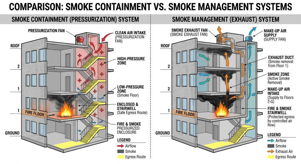
NFPA 92 covers two broad categories of smoke control: smoke containment systems and smoke management systems.
A. Smoke Containment Systems
Smoke containment systems keep smoke from entering specific areas using pressurization. They are commonly found in smaller enclosed spaces such as enclosed stairwells.
| Containment Approach | Application |
|---|---|
| Stairwell pressurization | Keep stairs tenable for egress |
| Elevator pressurization | Protect elevator hoistways |
| Zoned smoke control | Contain smoke to zone of origin |
| Vestibule pressurization | Create buffer between spaces |
| Smoke refuge area pressurization | Protect areas of refuge |
B. Smoke Management Systems
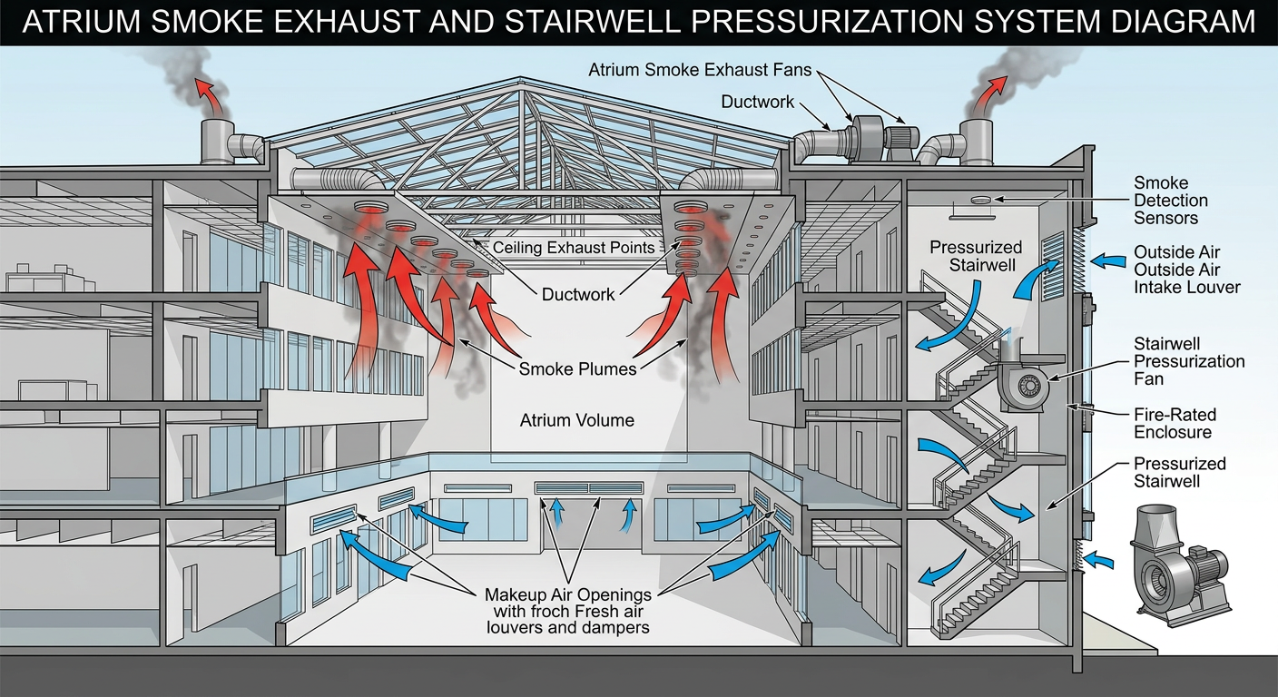
Smoke management systems maintain tenable environments in large-volume spaces or prevent smoke migration into surrounding spaces. They are typically installed in buildings with large, multilevel atriums.
| Management Approach | Application |
|---|---|
| Mechanical smoke exhaust | Remove smoke from large-volume spaces |
| Natural smoke ventilation | Use buoyancy of smoke for removal — see NFPA 204 and the applicable IBC smoke and heat venting provisions |
Key point: Mechanical smoke exhaust requires makeup air to be injected into the large space. Without makeup air, the space goes under negative pressure, which can raise door-opening forces and starve the exhaust of flow.
Pro Tip: Makeup air intakes must be located away from smoke exhaust points. Drawing smoke back into the building defeats the system.
◆ Section 3: Design Criteria — Containment and Management
NFPA 92 establishes design criteria that differ between containment and management systems.
A. Containment Systems — Minimum Pressure Difference
NFPA 92 Table 4.4.2.1.1 specifies the minimum pressure difference across smoke barriers:
| Building Type | Ceiling Height | Design Pressure Difference |
|---|---|---|
| Sprinklered | Any | 12.5 Pa (0.05 in. water) |
| Nonsprinklered | 2.7 m (9 ft) | 24.9 Pa (0.10 in. water) |
| Nonsprinklered | 4.6 m (15 ft) | 34.9 Pa (0.14 in. water) |
| Nonsprinklered | 6.4 m (21 ft) | 44.8 Pa (0.18 in. water) |
Key point: The minimum pressure difference for sprinklered buildings is 12.5 Pa regardless of ceiling height. For nonsprinklered buildings, the required pressure increases with ceiling height.
B. Containment Systems — Maximum Door Opening Force
NFPA 92 does not specify a fixed maximum pressure difference. The maximum pressure is derived from the door force limit, using door width and area, closer force, and pressure. NFPA 92’s calculation uses the 133 N (30 lbf) set-in-motion figure.
NFPA 101 §7.2.1.4.5 limits the forces required to open any door manually in a means of egress: no more than 15 lbf to release the latch, 30 lbf to set the door in motion, and 15 lbf to open the door to the minimum required width.
Key point: The pressure across a barrier must not result in a door-opening force that exceeds these limits. The calculated force includes the door closer force, not just the pressure load.
C. Management Systems — Makeup Air Velocity
NFPA 92 limits makeup air velocity to 1.02 m/s (200 fpm) during operation of a mechanical smoke exhaust system, where makeup air could reach or disturb the plume.
Key point: High makeup air velocity tilts the plume, increases entrainment, and disrupts the smoke layer. The limit applies where the makeup air could affect the plume, not universally.
D. System Activation
All smoke control systems must be activated automatically by detection devices—typically projected beam smoke detectors, spot-type smoke detectors, or sprinkler waterflow. Manual pull stations are not suitable for zoned systems because they do not identify the fire location.
The entire smoke control system must reach full operating conditions before the design smoke conditions are reached. This requires consideration of detection time, signal transfer time, and mechanical equipment response time.
Automatic Control: IBC §909.12.3.1 requires that mechanical smoke control systems using the pressurization, airflow, or exhaust method have completely automatic control.
Firefighter’s Smoke Control Panel: IBC §909.16 requires a firefighter’s smoke control panel (FSCP) for fire department emergency response purposes only, with manual control or override of automatic control. Control equipment must be UL 864 UUKL listed.
Pro Tip: Verify that the design accounts for startup time. A system that activates correctly but reaches full operation too late will not meet its tenability objective.
◆ Section 4: Design Methods for Large-Volume Spaces
NFPA 92 permits three methods of analysis for smoke management system design:
| Method | Application |
|---|---|
| Algebraic calculations | Basic atrium geometries; design scenarios |
| Computer simulations | Complex geometries; multiple variables |
| Physical modeling | Scale or full-size models |
A. Algebraic Calculations
The algebraic equations in NFPA 92 are useful for basic atrium geometries and design scenarios. When geometry is complex or many variables are at play, algebraic calculations become too conservative.
B. Computer Simulations
Most designers use computer simulations, which fall into two categories:
-
Zone fire models: Divide space into upper (smoke-filled) and lower (clean-air) layers
-
CFD models: Divide space into 3-D computational grid cells; track heat and smoke movement
CFD models require more computational power but provide visualization useful for smoke control design.
C. Design Fire
The design fire is the assumed fire size and growth rate for the analysis. NFPA 92 (annex, informative) provides recommended heat release rate per unit area (HRRPUA) values for specific occupancies. Verify the values against the edition you cite.
Key point: The design fire is a critical input. Too small, and the system will be undersized. Too large, and the system is over-designed and costly.
Pro Tip: For complex atriums or interconnected spaces, CFD modeling is often the practical choice. The ability to visualize smoke movement helps identify problems before construction.
◆ Section 5: Dedicated vs. Non-Dedicated Systems
NFPA 92 classifies systems as dedicated or non-dedicated.
| System Type | Description | Testing Frequency |
|---|---|---|
| Dedicated | Equipment operates exclusively for smoke control | Semiannual |
| Non-dedicated | Shares functions with building HVAC; changes mode during fire | Annual |
Key point: The testing frequency difference is significant. Dedicated systems require semiannual testing; non-dedicated systems require annual testing.
Pro Tip: Verify the system classification with the AHJ. The distinction affects both design and ongoing testing obligations.
◆ Section 6: Acceptance Testing
Acceptance testing demonstrates that the installed system meets the design and functions properly.
A. Pre-Testing Agreement
It is recommended that the building owner, designer, and AHJ meet during the planning stage to agree on design criteria and pass/fail performance tests. This helps avoid problems at final acceptance testing and facilitates obtaining the certificate of occupancy.
B. Operational and Acceptance Testing
| Step | Requirement |
|---|---|
| Operational test | Each component and subsystem tested prior to acceptance |
| Acceptance test | Demonstrates integrated system complies with design |
| Parameters measured | All parameters measured during acceptance testing |
| Normal mode | Building equipment placed in normal operating mode before testing |
| Standby power | Testing conducted on both normal and standby power if provided |
C. Complete Sequence Demonstrated
The complete smoke control sequence must be demonstrated for:
-
Normal mode
-
Automatic smoke control mode for first alarm
-
Transfer to standby power (if provided)
-
Return to normal
D. Special Inspector and Report Filing
The IBC requires a special inspector from an approved agency for smoke control system testing. The final acceptance test report must be filed with the fire code official, and an identical copy maintained in an approved location at the building (IBC §909.18.8.3.1).
Key point: Acceptance testing is not just checking that fans turn on. It verifies that the entire integrated system—detection, control, dampers, fans, and power—works together as designed.
Pro Tip: Document all acceptance test results and file the report with both the fire code official and the building.
◆ Section 7: Periodic Inspection, Testing, and Maintenance
NFPA 92 Section 8.6 establishes ongoing ITM requirements.
A. Testing Frequency
| System Type | Frequency |
|---|---|
| Dedicated systems | At least semiannually |
| Non-dedicated systems | At least annually |
B. What Must Be Determined
Periodic tests must determine airflow quantities and pressure differences at smoke barrier openings, air makeup supplies, and smoke exhaust equipment.
C. Documentation and Records
The results of tests must be documented in the operations and maintenance log and made available for inspection. The building owner is responsible for all system testing and maintaining records of periodic testing and maintenance.
Key point: When original acceptance documentation is unavailable, owners should confirm measurement locations and testing requirements with the AHJ.
Pro Tip: Retain acceptance test reports, design documents, and maintenance logs as permanent building records. Loss of documentation during ownership transfers can require costly re-commissioning.
◆ Section 8: Design Checklist for Smoke Control Systems
| Item | Status | Notes |
|---|---|---|
| Code requirement confirmed | ☐ | NFPA 101 occupancy chapter or building code |
| Design objective defined | ☐ | Tenability (maintaining conditions occupants can tolerate) or smoke layer interface (maintaining smoke layer above a set height) |
| System type selected | ☐ | Containment (pressurization) or management (exhaust) |
| Design approach selected | ☐ | Stairwell, zoned, atrium exhaust, etc. |
| Minimum pressure difference (containment) | ☐ | 12.5 Pa sprinklered; higher for nonsprinklered |
| Maximum door opening force (containment) | ☐ | 15 lbf latch; 30 lbf set in motion; 15 lbf open |
| Makeup air velocity (management) | ☐ | ≤1.02 m/s (200 fpm) where makeup air could reach plume |
| Design fire determined (management) | ☐ | Per NFPA 92 annex or engineering analysis |
| Analysis method selected | ☐ | Algebraic, computer simulation, or physical |
| Activation method | ☐ | Automatic on detection; FSCP with override |
| Control equipment listed | ☐ | UL 864 UUKL |
| Startup time considered | ☐ | System reaches full operation before design smoke conditions |
| Dedicated vs. non-dedicated | ☐ | Determines testing frequency |
| Pre-testing meeting with AHJ | ☐ | Agree on acceptance criteria |
| Acceptance test planned | ☐ | Normal, automatic, standby power, return to normal |
| Special inspector designated | ☐ | From approved agency per IBC |
| Report filed with fire code official | ☐ | Per IBC §909.18.8.3.1 |
| Periodic ITM scheduled | ☐ | Semiannual (dedicated); annual (non-dedicated) |
| Documentation retained | ☐ | Operations and maintenance log |
◆ Section 9: Common Mistakes and How to Avoid Them
| Mistake | Why It’s a Problem | How to Fix |
|---|---|---|
| No pre-testing agreement with AHJ | Acceptance testing disputes; delayed occupancy | Meet during planning stage |
| Door opening force exceeds limits | Occupants cannot open doors | Verify 15 lbf latch, 30 lbf set in motion, 15 lbf open |
| Makeup air velocity too high | Tilts plume, increases entrainment, disrupts smoke layer | Limit to 1.02 m/s (200 fpm) where makeup air could reach plume |
| Startup time overlooked | System reaches full operation too late | Calculate detection, signal, and mechanical times |
| Dedicated system tested annually | Violates NFPA 92 | Test dedicated systems semiannually |
| No records maintained | AHJ cannot verify compliance | Document in O&M log |
| Manual pull station used for activation | Cannot identify fire location | Use automatic detection for zoned systems |
| Acceptance test not on standby power | System may fail on backup | Test on both normal and standby power |
| No FSCP override | Firefighters cannot control system | Provide FSCP per IBC §909.16 |
| Report not filed with fire code official | Code violation | File with AHJ and maintain copy at building |
◆ Section 10: Conclusion
Smoke control systems are complex, integrated life safety systems that manage smoke movement to maintain tenability. They require careful design, coordinated control sequences, and rigorous testing to function when needed.
Key Takeaways:
-
NFPA 92 governs design, installation, and testing of smoke control systems; NFPA 101 and the building code determine when they are required.
-
Smoke containment systems use pressurization (stairwells, elevators, zones); smoke management systems use exhaust and makeup air (atriums, large spaces).
-
Minimum pressure difference is 12.5 Pa for sprinklered buildings; higher for nonsprinklered.
-
Door opening force limits are 15 lbf latch, 30 lbf set in motion, 15 lbf open (NFPA 101 §7.2.1.4.5).
-
Makeup air velocity is limited to 1.02 m/s (200 fpm) where makeup air could reach the plume.
-
Design methods include algebraic calculations, computer simulations (zone or CFD), and physical modeling.
-
Dedicated systems require semiannual testing; non-dedicated systems require annual testing.
-
Acceptance testing must demonstrate normal mode, automatic smoke control mode, standby power transfer, and return to normal.
-
Pre-testing agreement with the AHJ is recommended to avoid acceptance disputes.
-
The IBC requires a special inspector from an approved agency and filing the final report with the fire code official (IBC §909.18.8.3.1).
-
The building owner is responsible for system testing and maintaining records.
Take Action Today:
-
Confirm the code requirement and design objective for your smoke control system.
-
Verify minimum pressure difference and door opening force limits.
-
Confirm makeup air velocity is within limits where it could reach the plume.
-
Verify system activation is automatic with FSCP override per IBC §909.16.
-
Confirm startup time is considered in design.
-
Determine dedicated vs. non-dedicated classification.
-
Schedule a pre-testing meeting with the AHJ.
-
Plan acceptance testing including standby power.
-
Designate a special inspector from an approved agency and file the report with the fire code official.
-
Schedule periodic ITM (semiannual or annual).
-
Maintain documentation in the operations and maintenance log.
Continue Reading from Our Series:
-
Related guide: How to Design Fire Safety for Atriums and Large Volumes (Article 79)
-
Learn more: How to Design for Fire Safety in High-Rise Buildings (Article 77)
-
Read more: Understanding Smoke Control Systems in Commercial Buildings (Article 65)