Category: Building Codes

  • Fire Damper and Smoke Damper Requirements

    Fire Damper and Smoke Damper Requirements

    IMPORTANT DISCLAIMER: This guide references the International Building Code (IBC), Section 717 (Ducts and Air Transfer Openings) and Section 607 of the International Mechanical Code (IMC); UL 555, Standard for Fire Dampers; UL 555S, Standard for Smoke Dampers; UL 555C, Standard for Ceiling Dampers; NFPA 80, Standard for Fire Doors and Other Opening Protectives (2025 edition); and NFPA 105, Standard for Smoke Door Assemblies and Other Opening Protectives (2025 edition). These codes and standards vary by edition and are frequently amended by state and local jurisdictions. NFPA 80 Chapter 20 and NFPA 105 Chapter 7 were revised in the 2025 editions, including new requirements for operability, prevention of blockage, and remote inspection methods . The IBC damper provisions have been renumbered across editions (Section 717 in recent editions; Section 716 in earlier editions). Local amendments and the edition adopted by your Authority Having Jurisdiction (AHJ) always control. This guide is a starting point only. Always verify the specific requirements applicable to your project with your local AHJ.

    Fire dampers and smoke dampers are the critical link between HVAC systems and fire-rated assemblies. They protect duct penetrations through rated walls and floors, and they prevent smoke migration through ductwork. Unlike a wall or floor assembly, a damper has moving parts—and moving parts fail. A damper that is rusted, blocked, or improperly installed will not close when a fire starts, and the rated assembly it protects becomes a hole in the building’s passive fire protection.

    The IBC establishes where dampers are required and which type is required at each location. UL 555 and UL 555S establish the ratings that determine whether a damper can perform its intended function. NFPA 80 and NFPA 105 establish how dampers are inspected, tested, and maintained after installation.

    This article covers the types of dampers, their ratings, installation requirements, access provisions, and the testing that determines whether they work when needed.


    ◆ Section 1: Why Dampers Matter

    A duct penetration through a rated wall or floor is a breach in the building’s passive fire protection. The damper is the component that restores the rating—if it works.

    Factor Challenge
    Moving parts Dampers have blades, linkages, and actuators that can fail
    Concealed location Dampers are often above ceilings or in shafts, accessible only through access panels
    Corrosion and debris Rust, dust, and construction debris can bind damper components
    Improper installation A damper installed outside its listing will not perform as tested
    Missing access A damper that cannot be inspected cannot be verified as functional
    Static vs. dynamic mismatch A static damper in a dynamic system may not close against airflow

    Key point: The damper is a mechanical device. It must be installed correctly, maintained properly, and tested periodically. A damper that is never inspected is a damper that is assumed to work.

    Key Article: Article 134 — Firestop Systems: Testing, Listings, and Inspection

    Pro Tip: The most common damper failure is not a manufacturing defect—it is a damper that was never inspected because the access panel was obstructed or omitted.


    ◆ Section 2: Damper Types and Ratings

    The IBC recognizes five general types of dampers, each tested to a specific standard for a specific application .

    Damper Type Test Standard Primary Function Key Rating
    Fire Damper UL 555 Restrict passage of flame Hourly rating (1½ or 3 hour)
    Smoke Damper UL 555S Resist passage of smoke Leakage class (I, II, or III)
    Combination Fire/Smoke Damper UL 555 and UL 555S Both flame and smoke Hourly rating plus leakage class
    Corridor Damper UL 555S Protect corridor smoke barriers Leakage class
    Ceiling Radiation Damper UL 555C Protect floor-ceiling and roof-ceiling assemblies Assembly component

    Key point: The damper type must match the assembly being protected. A fire damper is not a smoke damper. A static damper is not a dynamic damper.

    Key Article: Article 131 — Fire-Resistance-Rated Assemblies and UL Listings

    Pro Tip: The IBC specifies which damper type is required at each location in Section 717.5 (walls) and Section 717.6 (horizontal assemblies) . Start there, not with the damper catalog.
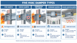
    Diagram comparing five damper types with test standards and applications


    ◆ Section 3: Fire Dampers — Static vs. Dynamic

    Fire dampers are classified as static or dynamic, and the distinction is one of the most consequential and most commonly misunderstood aspects of damper selection .

    A. Static Fire Dampers

    Static fire dampers are intended for use in static systems—HVAC systems that automatically shut down in the event of a fire. When airflow stops, the damper can close fully .

    B. Dynamic Fire Dampers

    Dynamic fire dampers are intended for use in dynamic systems—HVAC systems that continue to operate during a fire. The damper must be capable of closing against the air velocity and pressure produced by the system fan .

    Dynamic dampers must be tested and labeled for closure under the anticipated airflow and pressure conditions. They may also be used in static systems, but static dampers may not be used in dynamic systems .

    C. Airflow and Pressure Ratings

    Dynamic fire dampers are marked with airflow and closure pressure ratings. These ratings represent the maximum airflow and closure pressure the damper is tested to perform at .

    Rating Marking Minimum
    Airflow rating 1,000 fpm increments 2,000 fpm
    Closure pressure rating 2-inch w.g. increments 4-inch w.g.

    The mechanical designer specifies the minimum required airflow and pressure ratings on the mechanical plans. The inspector compares those values to the labeled ratings on the damper .

    D. Fire Damper Hourly Rating

    Fire dampers must have the minimum rating specified in IBC Table 717.3.2.1 (or IMC Table 607.3.2.1) :

    Type of Penetration Minimum Damper Rating
    Less than 3-hour fire-resistance-rated assemblies 1½ hour
    3-hour or greater fire-resistance-rated assemblies 3 hour

    Key point: A static damper installed in a system that continues to operate during a fire will not close. The airflow holds the blades open. The rated wall becomes an open hole.

    Pro Tip: Verify the system’s operating mode during a fire before selecting the damper. If the fan stays on, the damper must be dynamic and rated for the system’s airflow and pressure.


    ◆ Section 4: Smoke Dampers and Leakage Class

    Smoke dampers are designed to resist the passage of smoke. They are operated by electric or pneumatic actuators and controlled by smoke detectors and/or fire alarms .

    A. Leakage Class

    Smoke dampers are identified by leakage class—Class I, II, or III—based on the amount of air leakage through the closed damper .

    Class Leakage
    Class I Lowest leakage
    Class II Moderate leakage
    Class III Highest leakage

    B. Installation Distance

    Smoke dampers must be installed no more than 24 inches from the smoke barrier they protect, except where used to isolate air handling units .

    C. Smoke Damper Actuation

    Smoke dampers are controlled by smoke detection. The specific actuation method depends on the application :

    Condition Actuation Method
    Smoke damper in a corridor wall or ceiling May be controlled by a smoke detection system installed in the corridor
    Smoke damper in a duct served by an HVAC system with total-coverage smoke detection May be controlled by the smoke detection system
    Smoke damper in an air transfer opening Spot-type detector within 5 feet horizontally

    Key point: The smoke damper must be connected to the detection system that will actuate it. A damper that is installed but not connected to detection is not a smoke damper—it is a manual damper.

    Pro Tip: Verify the smoke damper actuation method against the IBC and the fire alarm design. The damper and the detection must be designed together.


    ◆ Section 5: Combination Fire/Smoke Dampers

    Combination fire/smoke dampers meet the requirements of both UL 555 and UL 555S . They are used where a wall, floor, or ceiling requires both a fire damper and a smoke damper .

    Feature Requirement
    Listings UL 555 (fire) and UL 555S (smoke)
    Actuation Heat (duct temperature) and smoke (detector)
    Leakage rating Class I or II typically
    Installation In a sleeve within the plane of the rated assembly

    Key point: A combination damper is not two dampers in one housing. It is a single device tested to both standards. It must be listed for both.

    Pro Tip: Combination fire/smoke dampers are available with electric heat release devices instead of fusible links. Electric release devices are resettable and allow the damper to close in a controlled manner rather than slamming closed .


    ◆ Section 6: Ceiling Radiation Dampers

    Ceiling radiation dampers protect floor-ceiling and roof-ceiling assemblies where ducts penetrate the ceiling membrane .

    A. UL 555C

    Ceiling dampers are tested to UL 555C . The standard evaluates the damper as a component of a specific hourly rated assembly, not as a standalone device with an hourly rating .

    B. Static vs. Dynamic Ceiling Dampers

    Ceiling dampers are investigated for dynamic closure where the HVAC system operates during a fire (e.g., smoke control systems) . Where airflow is stopped at the start of a fire, dynamic closure is not required .

    Important limitation: As of the 2018 IBC/IMC code development cycle, there were no UL listed dynamic ceiling radiation dampers . This means static ceiling dampers can only be used where the system is designed to shut down upon detection .

    C. Actuation

    Where a static ceiling radiation damper is installed, a smoke detector must be installed inside the duct or outside with sampling tubes within 5 feet of the damper . Air outlets and inlets must not be located between the detector and the damper .

    Key point: Ceiling radiation dampers are assembly components, not standalone rated devices. The assembly rating depends on the damper being installed per the listing.

    Pro Tip: For systems that must operate during a fire (exhaust, 100% outside air), verify whether a dynamic ceiling damper is available. If not, the system design may need to change to allow a static damper.


    ◆ Section 7: Installation Requirements

    Damper installation is governed by the listing and the manufacturer’s instructions. Several requirements are common across damper types.

    A. Sleeves and Clearances

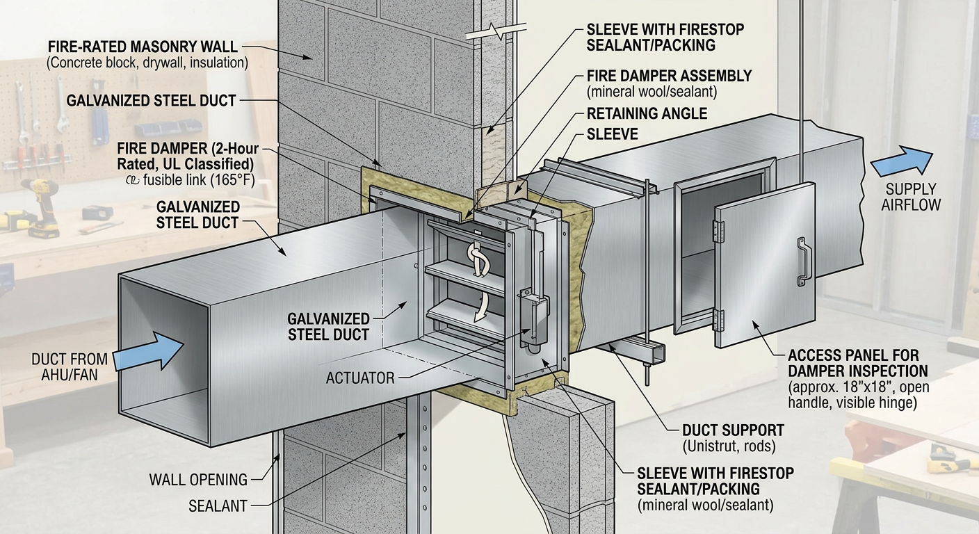
    Fire dampers and combination fire/smoke dampers are required to be enclosed in a sleeve and installed within the plane of the rated assembly . Smoke dampers may be installed directly in the duct and are not required to be enclosed in a sleeve .

    The opening clearance is typically a minimum of 1/4 inch larger than the damper/sleeve assembly, increasing 1/8 inch for each foot the damper exceeds 24 inches .

    B. Retaining Angles

    Retaining angles must overlap the partition by a minimum of 1 inch and must be installed on both sides of the wall or floor .

    C. Sealing

    The joints between the damper frame and the duct must be sealed to prevent air leakage . Sealant between the mounting angles and the partition is not required by UL but may be specified .

    D. Actuator Access

    The actuator and accessories must be accessible for testing, service, or replacement .

    Key point: The installation instructions are part of the listing. A damper installed in a configuration not shown in the manufacturer’s instructions is not a listed installation.

    Key Article: Article 134 — Firestop Systems: Testing, Listings, and Inspection

    Pro Tip: The annular space around the damper sleeve must be firestopped with a listed system, just like any other penetration. The firestop and the damper are separate systems that must both be compliant.


    ◆ Section 8: Access Panels and Identification

    Dampers must be accessible for inspection and maintenance.

    A. Access Requirements

    Fire dampers shall be provided with an approved means of access large enough to permit inspection and maintenance of the damper and its operating parts . The access openings shall not reduce the fire-resistance rating of the building assembly .

    B. Labeling

    Access points shall be permanently identified on the exterior by a label with letters not less than 0.5 inch in height reading: “FIRE DAMPER” or “FIRE/SMOKE DAMPER” .

    Access doors in ducts shall be tight-fitting and suitable for the required duct construction .

    Key point: The access panel is the only way to verify the damper works. A damper without access is a damper that will never be inspected.

    Pro Tip: Access panels are frequently obstructed by ceiling tiles, insulation, or stored materials. The label exists so that building occupants and maintenance staff can find the damper when they need to.


    ◆ Section 9: Inspection, Testing, and Maintenance

    Dampers require periodic inspection and testing after installation.

    A. NFPA 80 and NFPA 105

    NFPA 80 Chapter 20 (formerly Chapter 19) governs the installation, testing, and maintenance of fire dampers . NFPA 105 Chapter 7 governs smoke dampers .

    2025 edition changes: Both standards were revised in 2025 with new requirements for operability, prevention of blockage, replacement of dampers, visual inspection using remote methods, and a performance-based design option for inspection, testing, and maintenance .

    B. Testing Frequency

    For fire dampers, the 2019 NFPA 80 established the following frequency :

    Timing Frequency
    Initial 1 year after acceptance testing
    Subsequent Every 4 years
    Hospitals Every 6 years

    The 2025 editions include provisions for remote inspection methods where dampers are equipped for it, but the requirement for periodic physical inspection remains a point of debate .

    C. What Testing Involves

    Damper testing involves :

    • Visual confirmation of proper operation

    • Operating the damper via the actuator

    • Verifying closure (or opening, where applicable)

    • Checking for rust, blockage, or damage

    If the damper is not operable, repairs shall begin without delay .

    Key point: Testing is not a visual check from a distance. The damper must be operated and observed. A damper that “looks fine” may be seized.

    Pro Tip: Remote inspection via damper position indicators is permitted in some editions, but it does not replace physical inspection for detecting rust, blockage, or damage . Verify what your AHJ accepts.


    ◆ Section 10: Common Mistakes and How to Avoid Them

    Mistake Why It’s a Problem How to Fix
    Static damper in a dynamic system Airflow holds blades open; damper does not close Verify system operating mode; specify dynamic damper
    Smoke damper installed too far from barrier Leakage path bypasses the damper Install within 24 inches of the smoke barrier
    No access panel Damper cannot be inspected or maintained Provide labeled access panel; verify accessibility
    Access panel obstructed Damper effectively inaccessible Coordinate access with ceiling and finishes
    Damper not connected to detection Smoke damper does not actuate Verify actuation method and connection
    Improper sleeve or clearance Installation not per listing Follow manufacturer’s installation instructions
    Annular space not firestopped Rating lost at penetration Install listed firestop system
    No periodic testing Damper may be seized when needed Implement testing schedule per NFPA 80/105
    Assuming remote inspection is sufficient Rust, blockage, and damage not detected Physical inspection at required intervals

    ◆ Section 11: Conclusion

    Fire dampers and smoke dampers are the critical link between HVAC systems and fire-rated assemblies. They protect duct penetrations through rated walls and floors, and they prevent smoke migration through ductwork.

    The IBC establishes where dampers are required. UL 555, UL 555S, and UL 555C establish the ratings that determine whether a damper can perform its function. NFPA 80 and NFPA 105 establish how dampers are inspected, tested, and maintained after installation.

    A damper is a mechanical device. It has moving parts, and moving parts fail. The rated assembly it protects is only as good as the damper’s installation and maintenance.

    Key Takeaways:

    1. The IBC specifies the damper type required at each location in Section 717.5 (walls) and Section 717.6 (horizontal assemblies) .

    2. Static vs. dynamic is critical—a static damper in a system that operates during a fire will not close .

    3. Dynamic dampers are marked with airflow and closure pressure ratings that must meet or exceed the system design .

    4. Fire damper hourly rating is 1½ hour for less than 3-hour assemblies; 3 hour for 3-hour or greater .

    5. Smoke dampers are rated by leakage class (I, II, or III) and must be installed within 24 inches of the smoke barrier .

    6. Combination fire/smoke dampers must be listed to both UL 555 and UL 555S .

    7. Ceiling radiation dampers are tested to UL 555C as assembly components .

    8. Access panels must be provided and labeled “FIRE DAMPER” or “FIRE/SMOKE DAMPER” .

    9. NFPA 80 and NFPA 105 govern testing: 1 year after acceptance, then every 4 years (6 years for hospitals) .

    10. Remote inspection does not replace physical inspection for detecting rust, blockage, or damage .

    Take Action Today:

    1. Verify the damper type required at each rated penetration.

    2. Confirm whether the system is static or dynamic; specify dampers accordingly.

    3. Verify dynamic damper airflow and pressure ratings against system design.

    4. Confirm smoke dampers are within 24 inches of smoke barriers.

    5. Verify access panels are provided, labeled, and accessible.

    6. Confirm dampers are connected to the correct detection system.

    7. Implement the NFPA 80/105 testing schedule.

    8. Train maintenance staff on damper operation and inspection.

    9. Coordinate firestop and damper installations as separate but complementary systems.


    Continue Reading from Our Series:

    • Related guide: Fire-Resistance-Rated Assemblies and UL Listings (Article 131)

    • Learn more: Firestop Systems: Testing, Listings, and Inspection (Article 134)

    • Read more: Grease Duct Design and Fire Safety (Article 135)

    [End of Article]
  • Firestop Systems: Testing, Listings, and Inspection

    Firestop Systems: Testing, Listings, and Inspection

    IMPORTANT DISCLAIMER: This guide references the International Building Code (IBC), Chapter 7 (Fire and Smoke Protection Features), specifically Section 714 (Penetrations) and Section 715 (Joints and Voids), plus Section 710 (Smoke Barriers), Section 717 (Ducts and Air Transfer Openings), and Chapter 17 (Special Inspections); ASTM E814, Standard Test Method for Fire Tests of Penetration Firestop Systems; ASTM E1966, Standard Test Method for Fire-Resistive Joint Systems; ASTM E2307, Standard Test Method for Determining Fire Resistance of Perimeter Fire Barriers; ASTM E2174, Standard Practice for On-Site Inspection of Installed Firestop Systems; ASTM E2393, Standard Practice for On-Site Inspection of Installed Fire Resistive Joint Systems and Perimeter Fire Barriers; UL 1479; UL 2079; NFPA 101, Life Safety Code; and the International Fire Code (IFC), Chapter 7. These codes and standards vary by edition and are frequently amended by state and local jurisdictions. Section numbers shift between IBC editions. Local amendments and the edition adopted by your Authority Having Jurisdiction (AHJ) always control. This guide is a starting point only. Always verify the specific requirements applicable to your project with your local AHJ.

    Firestopping is where rated assemblies most often fail. A listed firestop product does not create a compliant installation. The complete field condition must match the applicable system listing. The gap between the tested assembly and the installed assembly is where ratings are lost, and firestopping is the most common point of failure in that gap.

    This article covers the testing standards that govern firestop systems, the components of a listed system, the code provisions that decide when each rating is required, the inspection standards that verify compliance, and the documentation and maintenance practices that keep a firestop program working for the life of the building.


    ◆ Section 1: Why Firestop Systems Fail

    Firestop failures occur for predictable reasons, and understanding them is the first step toward preventing them.

    Failure Mode Why It Happens
    Wrong system selected The field condition does not match the listed system’s tested parameters
    Wrong annular space Gap between penetrant and opening is outside the listing’s permitted range
    Missing backing material Mineral wool or other backing is required but omitted
    Insufficient sealant depth Sealant applied too thin to achieve the listed rating
    Substituted products A different product is used than the one tested in the system
    Unsealed mullion cavities Gaps at mullions, columns, or slab edges are left unprotected
    Later additions not restored New cables or pipes are added through an existing firestop and the seal is not rebuilt
    No documentation Compliance cannot be verified during inspection or after turnover

    Key point: The rating belongs to the complete system: every component, every dimension, every material. If the field condition does not match the listing, it is not a tested system.

    Key Article: Article 131 — Fire-Resistance-Rated Assemblies and UL Listings

    Pro Tip: The most common field failure is not a missing product. It is a product installed in a configuration that was never tested.


    ◆ Section 2: Regulatory Framework

    Firestop systems are governed by a coordinated set of code provisions, test standards, and inspection practices.

    Standard Scope Key Provisions
    IBC §714 Penetrations Firestop systems required for through-penetrations and membrane penetrations
    IBC §715 Joints and voids Fire-resistant joint systems required at rated joints; perimeter fire containment at the floor/exterior wall intersection
    IBC §710 Smoke barriers Additional requirements for penetrations and joints in smoke barriers
    IBC §717 Ducts and air transfer openings Fire and smoke dampers; firestopping around damper sleeves and ducts
    ASTM E814 / UL 1479 Through-penetration firestop systems F-rating, T-rating, L-rating (UL 1479)
    ASTM E1966 / UL 2079 Fire-resistive joint systems Hourly rating; movement capability
    ASTM E2307 Perimeter fire barriers F-rating at the floor/exterior wall intersection
    ASTM E2174 Inspection of installed firestop systems On-site inspection procedures
    ASTM E2393 Inspection of joint systems and perimeter barriers On-site inspection procedures
    IFC Ch. 7 Existing buildings Owner’s responsibility to maintain fire-resistance-rated construction

    Key point: The IBC establishes when firestopping is required. The ASTM and UL standards establish how systems are tested and how installations are inspected. The IFC keeps them intact after occupancy.

    Key Article: Article 64 — Firestopping and Penetration Sealing — Essential Details

    Pro Tip: ASTM E2174 and E2393 are referenced in IBC Chapter 17 as the standards for special inspection of firestop and joint systems.

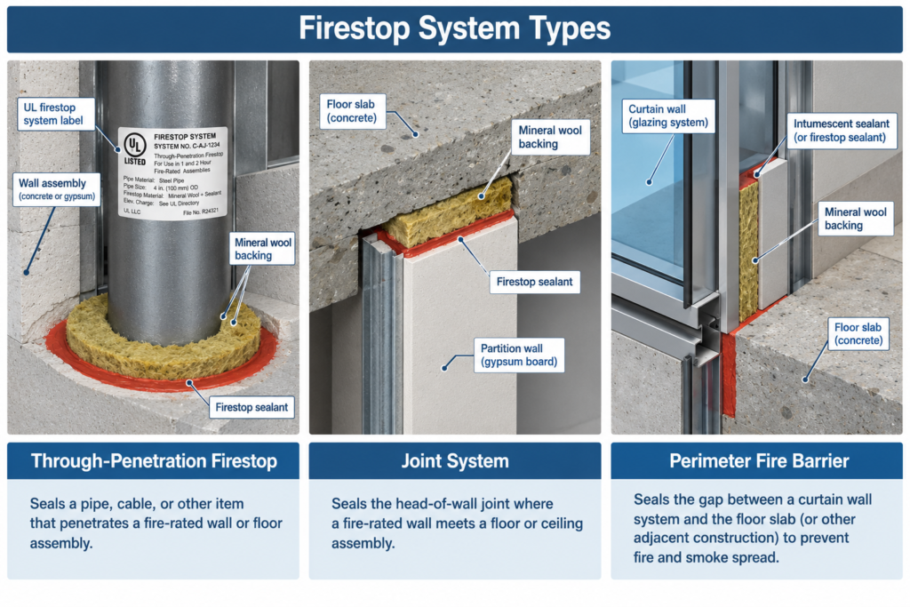
    Diagram showing through-penetration, joint, and perimeter firestop system types


    ◆ Section 3: Testing Standards — What Each One Covers

    A. ASTM E814 / UL 1479 — Through-Penetration Firestop Systems

    ASTM E814 is the test method for firestop systems used in openings in fire-resistive walls and floors. The test evaluates:

    • F-rating: the time flames do not pass through the system
    • T-rating: the time for the unexposed side to reach 325°F above ambient (the test also tracks temperature at the penetrating item)

    The test also includes a hose stream test, which checks that the system stays in place when it is struck by water after fire exposure. The F-rating is based on flame occurrence on the unexposed surface, while the T-rating is based on temperature rise.

    UL 1479 adds optional ratings that matter for smoke-rated construction:

    • L-rating: air leakage through the system at ambient and elevated temperatures, relevant to smoke barriers and smoke partitions
    • W-rating: resistance to water passage, relevant where water tightness is specified

    Important limitation: ASTM E814 does not cover membrane penetrations of floor-ceiling or roof-ceiling assemblies, which are evaluated as part of the ASTM E119 assembly test, nor membrane penetrations of load-bearing walls.

    B. ASTM E1966 / UL 2079 — Fire-Resistive Joint Systems

    ASTM E1966 evaluates joint systems designed for use with fire-rated floors and walls. The test measures:

    • Movement capability of the joint system, including cycling
    • Loadbearing capacity (where applicable)
    • Ability to prohibit passage of flames and hot gases
    • Transmission of heat through the system
    • Hose stream resistance (for wall joints)

    UL 2079 includes cycling tests that classify a joint as nonmoving or moving (for example, thermal, wind sway, or seismic movement). The movement class must match what the joint will actually experience.

    Important limitation: The test does not provide quantitative information about smoke or gas leakage through the joint system. Where smoke resistance is required, UL 2079 L-rating data is used.

    C. ASTM E2307 — Perimeter Fire Barriers

    ASTM E2307 measures the perimeter fire barrier’s ability to maintain a seal during deflection and deformation of the exterior wall and floor assemblies. The test subjects the perimeter joint to:

    • Fire exposure from an interior compartment fire
    • Flame plume from a window burner below
    • Movement of the wall and slab

    Important limitation: The test does not measure flame spread over the exterior face, within combustible cores, or over interior surfaces. Those are addressed separately (see NFPA 285 and Article 133).

    Key point: Each test standard addresses a specific condition. A joint system tested to ASTM E1966 is not a substitute for a perimeter fire barrier tested to ASTM E2307.

    Key Article: Article 133 — Curtain Walls and Fire Safety Performance

    Pro Tip: The T-rating is often misunderstood. It measures temperature rise on the unexposed side, not just flame passage. A system with an F-rating but no T-rating may still allow enough heat transfer to ignite materials on the non-fire side.


    ◆ Section 4: When Each Rating Is Required (Code Triggers)

    Selecting a system starts with knowing which ratings the code demands for the assembly being penetrated.

    Condition Typical Requirement Notes
    Through-penetration of a rated wall F-rating not less than the wall’s hourly rating Verify against current IBC §714
    Through-penetration of a rated floor or floor-ceiling assembly F-rating and T-rating Limited exceptions apply, for example penetrations contained within a wall cavity or certain small penetrating items
    Membrane penetration (such as outlet boxes) Tested assembly listing, or prescriptive limits on box size, spacing, and sealing Usually protected by listed putty pads or by assembly-specific limits
    Penetration of a smoke barrier or smoke partition System that limits smoke passage, often an L-rating per UL 1479 Check IBC §710 and the adopted NFPA 101 provisions
    Joint in a rated assembly Joint system tested to ASTM E1966 or UL 2079 Rating must be at least that of the assembly
    Floor / exterior wall intersection Perimeter fire barrier tested to ASTM E2307 F-rating not less than the floor assembly
    Duct penetration Damper per IBC §717, with the sleeve or angle installed per the damper listing Firestop at the damper annular space must also match a listing

    The IBC also allows limited prescriptive methods, for example small noncombustible items through concrete or masonry with a tight annular space filled with approved noncombustible material. These exceptions are narrow. Confirm the limits in the edition adopted by your AHJ before relying on them.

    Key point: The F-rating, T-rating, and L-rating answer different questions: flame, heat, and smoke. Specify the ones the assembly actually requires.

    Pro Tip: Put the required F, T, and L ratings on the penetration schedule for every condition. Installers cannot select a compliant system from a rating that is not stated.


    ◆ Section 5: Components of a Listed System

    A listed firestop system includes every component required to achieve the rating. The listing specifies each component, and substitutions void the rating.

    Component Function Common Materials
    Backing material Supports sealant during installation; insulates Mineral wool, ceramic fiber
    Sealant Primary fire barrier; intumescent or non-intumescent Silicone, water-based, intumescent
    Fill material Fills large voids; provides insulation Mineral wool, foam
    Collars and wraps Protect plastic pipe penetrations Intumescent wraps, metal collars
    Putty Seals complex configurations and membrane penetrations Moldable intumescent putty
    Composite sheets Seal large openings Elastomer bonded to steel
    Modules Seal cable tray and cable bundle penetrations Elastomeric modules in frames
    Mechanical devices Allow cables to be added or removed without rebuilding the seal Pass-through devices, sleeves
    Joint materials Seal linear joints and head-of-wall conditions Spray, sealant, mineral wool with coating, preformed profiles

    Key point: The listing specifies not just the products but their arrangement, thickness, compression, and annular space limits. A system installed with the correct products in the wrong configuration is not a tested system.

    Pro Tip: The UL Product iQ database and other listing directories (such as Intertek’s) provide installation requirements, drawings, and descriptions for each listed system. Require the contractor to provide the specific system listing for each penetration condition.


    ◆ Section 6: Matching a System to the Field Condition

    A listing is only usable when every variable in the field matches it. The following parameters must be checked together.

    Parameter What to Verify
    Assembly type and rating Wall or floor, construction type, and hourly rating
    Substrate Concrete, masonry, gypsum, or other. Thickness must be within the tested range
    Penetrant type Steel pipe, copper, plastic, insulated pipe, cable, cable tray, conduit, duct
    Penetrant size and fill Diameter, number of items, and cable fill ratio in trays and sleeves
    Annular space Within the listing’s permitted range
    Sleeve or no sleeve Listing may require or prohibit a sleeve
    Insulation Pipe insulation type and whether it continues through the system
    Ratings required F, T, and L as applicable
    Movement Will the penetrant move or vibrate? Some listings limit this

    Annular Space, Backing, and Sealant Depth

    These three parameters are where most firestop failures occur.

    A. Annular Space. The annular space is the gap between the penetrant (pipe, cable, conduit) and the edge of the opening. Each listing specifies a permitted range.

    Condition Why It Matters
    Too small May not allow sufficient sealant or backing
    Too large May exceed the listing’s tested maximum
    Irregular May not match the tested configuration

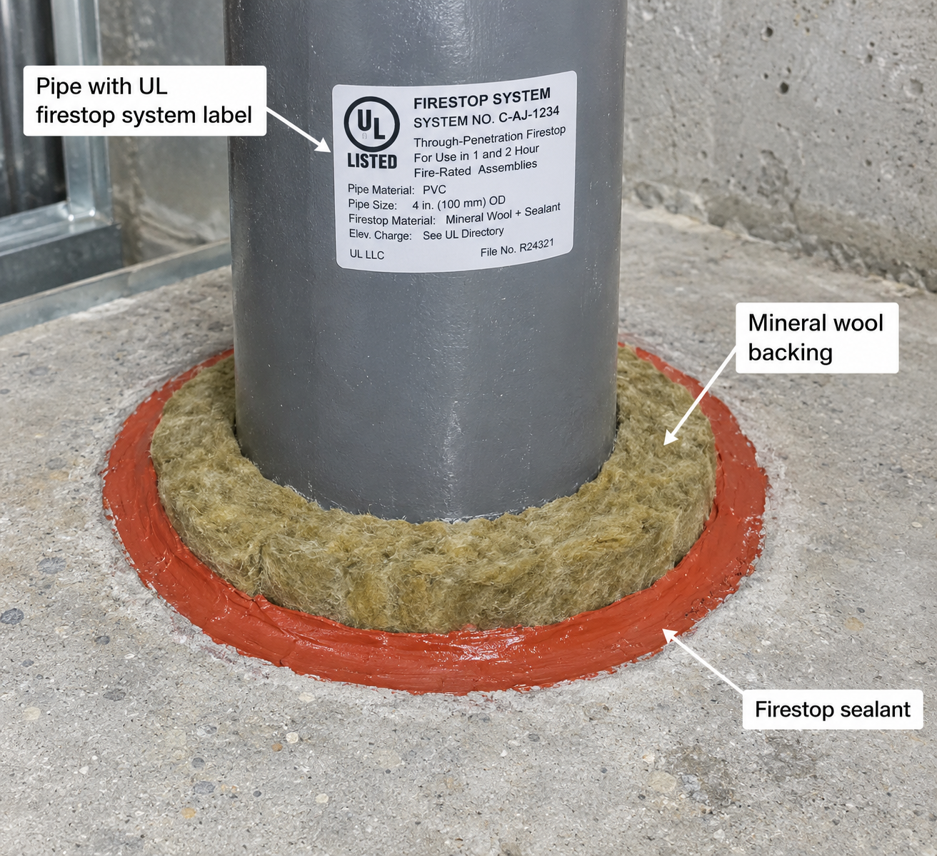
    B. Backing Material. Mineral wool or ceramic fiber backing is often required to support the sealant during installation and curing, provide insulation against heat transfer, and maintain the sealant at the required depth. The listing specifies the type, density, and compression of the backing material.

    C. Sealant Depth. Sealant must be applied at the depth specified in the listing. A sealant applied too thin will not achieve the rating. The listing also specifies the required sealant type, and substituting a different product voids the system.

    Key point: Inspectors verify annular space within permitted limits, backing material type and compression, and sealant depth that meets the listing.

    Pro Tip: Photograph the installed system before it is concealed. This documentation is essential for special inspection records and future maintenance.


    ◆ Section 7: Special Conditions That Cause Problems

    Some conditions are repeatedly mishandled because the standard details do not fit them.

    • Plastic pipe. Combustible pipe burns away in a fire, so the system must close the opening. Collars and wraps are typically listed for specific pipe materials, diameters, and wall thicknesses.
    • Insulated pipe. Insulation may need to continue through the opening, or be removed and replaced by a listed material. Follow the listing.
    • Cable tray and bundled cable. Fill ratio, tray type, and cable type affect the listing. Overfilled trays often fall outside the tested range.
    • Duct penetrations. The damper listing governs the sleeve or angle. The firestop at the annular space must also match a listing.
    • Head-of-wall and joint conditions. Movement class and joint width must match the E1966 / UL 2079 listing. Deflection at the top of a wall is a frequent failure point.
    • Membrane penetrations. Outlet boxes and similar devices must follow the assembly listing or the prescriptive limits, including back-to-back spacing rules.
    • Smoke barriers. The rating must address smoke passage, not just fire. Confirm the L-rating requirement.
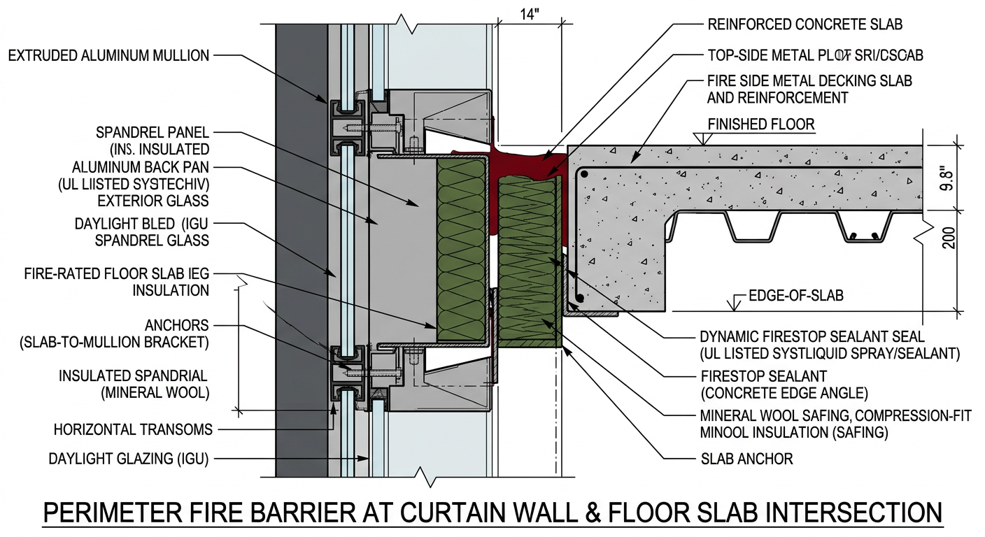
    • Curtain wall and perimeter conditions. Safing insulation and perimeter barrier systems must be tested to ASTM E2307, and mullion cavities are often left open.
    • Abandoned and re-entered penetrations. Removing cables or adding new ones through an existing firestop breaks the seal unless it is restored.
    • Temporary firestopping. During construction, openings may need temporary protection until the final system is installed. Plan this early, particularly on phased projects.

    Pro Tip: Walk the building before ceilings close and look for the condition your standard details do not cover. That is where the problems are.


    ◆ Section 8: Inspection Standards

    Firestop inspection is governed by two ASTM standards, both referenced in IBC Chapter 17.

    A. ASTM E2174 — Through-Penetration Firestop Systems

    ASTM E2174 establishes procedures to inspect firestop products and systems, including methods for field verification. The practice is referenced in IBC Chapter 17, Special Inspections. It provides methods by which qualified inspectors verify that required firestops have been installed and that installations are in accordance with the inspection documents.

    B. ASTM E2393 — Joint Systems and Perimeter Fire Barriers

    ASTM E2393 establishes procedures to inspect fire-resistive joint systems and perimeter joint protection. The standard references ASTM E1966 and UL 2079 for joint systems and ASTM E2307 for perimeter joint protection. The practice provides methods by which qualified inspectors verify that required joint systems have been installed and that installations are in accordance with the inspection documents.

    C. What Inspectors Verify

    Verification Detail
    System selection Does the installed condition match a listed system?
    Annular space Within the listing’s permitted range?
    Backing material Correct type and compression?
    Sealant depth Meets the listing’s required depth?
    Product match Same products as the listing, not substitutes?
    Labeling Is the system tagged or labeled?

    D. Special Inspection Under the IBC

    IBC Chapter 17 requires special inspection of firestopping in many buildings. The trigger depends on the edition and on local amendments, and it commonly includes high-rise buildings and buildings assigned to Risk Category III or IV. Confirm the applicability and the subsection numbering in your adopted edition.

    Special inspection is separate from the contractor’s own quality control. The inspector should be independent of the installer and qualified for firestop work. Inspection agencies typically demonstrate qualifications through third-party accreditation and trained personnel. Confirm what your AHJ and project specifications accept.

    Key point: Inspection is not a formality. It is the mechanism that verifies the installed system matches the tested system.

    Pro Tip: The International Firestop Council’s Inspector Pocket Guide provides step-by-step field inspection checklists and guidance for Engineering Judgments.


    ◆ Section 9: Destructive Verification and Sampling

    ASTM E2174 and E2393 are mostly visual inspection procedures, but they also provide for destructive verification, which is the sampling of installed systems to confirm the installation matches the listing.

    A. What Destructive Verification Involves

    • Removing a sample of the installed system
    • Measuring annular space, sealant depth, and backing compression
    • Comparing the installation to the listing
    • Repairing the sampled location with the same listed system, and documenting the repair

    B. When It Is Used

    Destructive verification is applied when the inspection documents, project specifications, or the AHJ call for it. The scope and sampling frequency depend on the building’s risk category, height, and the AHJ’s requirements. Confirm early whether your project requires it.

    Key point: Destructive verification is not punitive. It is the only way to confirm that concealed installations meet the listing. A system that looks correct on the surface may fail when measured.

    Pro Tip: Coordinate destructive verification with the contractor and the AHJ before installation begins. Sampling locations should be selected to represent the range of conditions on the project, and the repair of each sampled location must be built into the scope.


    ◆ Section 10: Documentation and Close-Out

    Documentation turns a firestop installation into a facility asset.

    A. What the Documentation Package Should Include

    Document Purpose
    Penetration schedule Lists each penetration type, size, required ratings, and applicable system
    System listings Copies of the UL or Intertek listings for each system used
    Installation records Date, location, installer, and system used
    Inspection reports ASTM E2174/E2393 reports, including destructive verification
    Photographs Before concealment, keyed to drawings
    Red-lined as-builts Marked-up drawings showing installed systems
    Engineering Judgments For conditions not covered by a listed system
    Deficiency log Findings, corrections, and re-inspection results

    B. Labeling and Identification

    Firestop systems should be tagged or labeled to identify the system used. This supports future maintenance and renovation work, and it allows inspectors to verify compliance after the fact.

    Key point: The documentation package is not just for close-out. It is for the life of the building. When a future renovation penetrates a rated assembly, the documentation tells the contractor what system was used and how to restore it.

    Pro Tip: Require the firestop contractor to organize the submittal by condition, not by product. A condition-based submittal matches how the work is actually installed and inspected.


    ◆ Section 11: Maintenance, Alterations, and Re-Entry

    The firestop program does not end at occupancy. Penetrations are altered more often than almost any other part of a building, especially cabling.

    A. Owner Responsibility

    The IFC places responsibility on the owner to maintain fire-resistance-rated construction, including penetrations and joints, in good repair. After a rated assembly is breached, the opening must be restored with a listed system. Verify the specific provisions in your adopted fire code.

    B. Managing Alterations

    • Require a penetration permit or work-order process so that no one cores or cuts a rated assembly without notifying facilities.
    • Use the original documentation to identify the system that was installed.
    • Restore each opening with a listed system that matches the new field condition.
    • Update the penetration schedule, photographs, and labels after the work.
    • Inspect the new work, and re-inspect existing systems the work may have disturbed.

    C. Cabling and Re-Entry

    Low-voltage and data cabling is the most frequent source of broken firestops. Options include:

    • Listed pass-through devices designed for adding and removing cables
    • Listed modular systems that can be re-opened and resealed
    • Restoration of the original system after each cable change, performed by a trained installer

    D. Periodic Review

    A periodic walk-through of accessible rated assemblies, such as above-ceiling areas, shafts, and mechanical rooms, can find unprotected penetrations before an inspector or a fire does.

    Key point: A firestop system that was compliant at turnover is only compliant today if every alteration since then was restored and documented.

    Pro Tip: Require that the firestop contractor for any alteration work be qualified, even for small jobs. Small penetrations are where most unlisted repairs happen.


    ◆ Section 12: Contractor Certification Programs

    Two programs provide third-party verification of a firestop contractor’s quality management system.

    A. UL Solutions Qualified Firestop Contractor Program

    The UL Solutions Qualified Contractor Program is a quality management audit-based service for installers of firestop systems. To participate, a contractor must:

    • Appoint and employ a Designated Responsible Individual (DRI) with applicable expertise
    • Pass the UL Solutions Firestop Exam or NFCA industry exam
    • Maintain a 10-element management system evaluated through an annual audit

    The program covers review of project design and construction document requirements, installation, training and field quality, and documentation and record keeping. Qualified contractors are listed in the UL Solutions online certifications directory and can obtain a Master Audit Certificate of Compliance (MACC) for specific projects.

    B. FM 4991 — Approval of Firestop Contractors

    FM 4991 establishes requirements for approved contractors who install firestop systems. The standard is maintained by FM Approvals and is updated periodically (confirm the current edition on the FM Approvals website).

    Key point: Both programs provide third-party auditing of a contractor’s training, methods, and documentation. Many specifications and some AHJs now require one of them, and they materially reduce inspection findings.

    Pro Tip: When evaluating firestop contractors, ask for their UL or FM certification and the name of their DRI. The certification is a signal of quality management, not just technical knowledge.


    ◆ Section 13: Engineering Judgments

    Where field conditions deviate from tested listings, an Engineering Judgment (EJ) may be developed.

    A. What an EJ Is

    A firestop Engineering Judgment is a technical evaluation based on tested systems, engineering principles, and applicable guidance. It is intended to address specific firestop performance considerations and provide schematic, representative details.

    B. What an EJ Is Not

    The International Firestop Council (not to be confused with the International Fire Code, also abbreviated IFC) has issued a position statement clarifying that EJs are not:

    • As-built drawings
    • Coordination drawings
    • Complete construction documents
    • Code compliance evaluations for surrounding construction
    • A substitute for the Registered Design Professional’s project responsibilities

    C. Who Prepares EJs

    EJs should be prepared by:

    • The manufacturer’s qualified technical personnel
    • A knowledgeable registered Professional Engineer
    • A Fire Protection Engineer
    • An independent testing agency

    Key point: Use EJs only where no tested and listed system exists for the application. Many AHJs expect EJs to follow the International Firestop Council guidelines for evaluating firestop engineering judgments and to be submitted for review.

    Pro Tip: Adding unnecessary detail to an EJ can create problems, including increased costs, delayed approvals, and confusion. Keep the EJ focused on the firestop condition being evaluated.


    ◆ Section 14: Specifying and Coordinating Firestopping

    Many firestop problems begin in the specification and the schedule, long before installation.

    A. Specification

    • Use a dedicated specification section (CSI MasterFormat Division 07, Firestopping, with joint firestopping often in its own section).
    • Require listed systems only, with F, T, and L ratings stated.
    • Require submittals organized by condition, with the listing for each.
    • Require the contractor certification and inspection provisions covered above.
    • Define who is responsible for firestopping each trade’s penetrations, so that no trade assumes someone else will do it.

    B. Coordination

    • Hold a pre-installation meeting with the firestop contractor, the trades, the special inspector, and the AHJ if required.
    • Consider a mockup of representative conditions for early review.
    • Sequence firestopping so that systems are installed and inspected before ceilings, insulation, and finishes conceal them.
    • Coordinate with other trades whose work interacts with firestopping, including mechanical, electrical, plumbing, and low-voltage.

    Pro Tip: Inspections that happen after concealment are expensive. Schedule firestop inspections as hold points before the work is covered.


    ◆ Section 15: Design Checklist for Firestop Systems

    Item Status Notes
    Penetration schedule prepared ☐ Organized by condition, not product
    Required F, T, and L ratings identified ☐ Based on assembly, smoke barrier status, and AHJ requirements
    System listings selected ☐ UL or Intertek listings for each condition
    Substrate, penetrant, and fill verified ☐ Match every listing parameter
    Annular space verified ☐ Within listing’s permitted range
    Backing material specified ☐ Type, density, compression per listing
    Sealant type and depth specified ☐ Per listing; no substitutions
    Smoke barrier penetrations addressed ☐ L-rating where required
    Duct and damper penetrations coordinated ☐ Per damper and firestop listings
    Perimeter fire barrier specified ☐ ASTM E2307 tested system
    Joint systems specified ☐ ASTM E1966 / UL 2079; movement class matches
    Special inspection identified ☐ ASTM E2174/E2393; IBC Chapter 17
    Destructive verification planned ☐ Sampling and repairs per AHJ requirements
    Documentation package defined ☐ Listings, records, photos, as-builts
    Labeling requirement defined ☐ Tag or label for each system
    Contractor certification required ☐ UL Qualified or FM 4991
    Engineering Judgments anticipated ☐ For unique conditions; prepared by qualified entity
    Alteration and re-entry process defined ☐ Permit process, restoration, and documentation

    ◆ Section 16: Common Mistakes and How to Avoid Them

    Mistake Why It’s a Problem How to Fix
    Selecting a system that doesn’t match the field condition Installation is not a tested system Match every parameter: annular space, substrate, penetrant type
    Substituting products Voids the listing Use only the products specified in the listing
    Insufficient sealant depth Rating not achieved Verify depth per listing
    Missing backing material Sealant may not perform Require backing per listing
    Ignoring the T-rating in floors Heat transfer can ignite materials on the unexposed side Specify F and T ratings where required
    Ignoring smoke barrier requirements Fire rating alone does not limit smoke passage Identify smoke barriers and specify L-rating where required
    No documentation Compliance unverifiable Maintain penetration schedule, listings, and inspection records
    Using a joint system for a perimeter barrier Different test, different exposure Specify ASTM E2307 for perimeter barriers
    Joint movement class doesn’t match the condition Seal fails under real movement Match the UL 2079 movement class to the joint
    Skipping special inspection IBC violation Engage an approved inspection agency
    Inspecting after concealment Defects cannot be seen or measured Make firestop inspection a hold point
    Engineering Judgment used as as-built EJ issuer accepts conditions never reviewed Keep EJs focused on firestop performance
    No contractor certification Quality management unverified Require UL Qualified or FM 4991
    Unrestored penetrations after cable work Seal is broken without anyone noticing Use a work-permit process and listed re-entry systems
    Failure to re-inspect after alterations New penetrations break compliance Re-inspect and document after any work

    ◆ Section 17: Conclusion

    Firestop systems are where rated assemblies most often fail. The gap between the tested assembly and the installed assembly is where ratings are lost, and firestopping is the most common point of failure in that gap.

    The testing standards (ASTM E814 / UL 1479 for penetrations, ASTM E1966 / UL 2079 for joints, and ASTM E2307 for perimeter barriers) define the systems. The inspection standards (ASTM E2174 and E2393) verify that installed systems match the listings. Contractor certification, documentation, and a disciplined alteration process close the loop and keep the system compliant long after turnover.

    Firestopping is not a product. It is a system, and it is only as good as its installation and its maintenance.

    Key Takeaways:

    • Firestop systems are tested as complete systems, not individual products.
    • ASTM E814 covers through-penetrations; ASTM E1966 covers joints; ASTM E2307 covers perimeter barriers.
    • F-rating is flame passage; T-rating is temperature rise on the unexposed side; L-rating is air leakage and matters for smoke barriers.
    • Specify the ratings the assembly actually requires, and state them on the penetration schedule.
    • Annular space, backing material, and sealant depth are the three most common points of failure.
    • ASTM E2174 and E2393 define inspection procedures for firestop and joint systems.
    • IBC special inspection applies in many buildings, and destructive verification is used where the inspection documents or the AHJ call for it.
    • Documentation turns a firestop installation into a facility asset.
    • UL Qualified Firestop Contractor and FM 4991 provide third-party verification of contractor quality management.
    • Engineering Judgments are technical evaluations, not as-built drawings.
    • Every later alteration must be restored with a listed system and documented.

    Take Action Today:

    1. Prepare a penetration schedule organized by condition, with required F, T, and L ratings.
    2. Select listed systems that match each field condition.
    3. Verify annular space, backing, and sealant depth during installation.
    4. Identify smoke barriers and confirm L-rating requirements.
    5. Engage an approved inspection agency for ASTM E2174/E2393 inspections, and make inspection a hold point before concealment.
    6. Plan destructive verification sampling and repairs with the AHJ.
    7. Require a documentation package including listings, records, and photos.
    8. Specify UL Qualified Firestop Contractor or FM 4991 certification.
    9. Require Engineering Judgments only for unique conditions, prepared by qualified entities.
    10. Set up a work-permit and re-entry process, and re-inspect after any alterations.

    What I changed, and what to verify

    Added sections: code triggers for each rating (new Section 4), matching a system to the field condition (new Section 6), special conditions such as plastic pipe, cable tray, ducts, and head-of-wall (new Section 7), maintenance, alterations, and re-entry (new Section 11), and specifying and coordinating firestopping (new Section 14). I also added L-rating and W-rating, UL 2079 movement classes, smoke barrier penetrations (IBC §710), and duct and damper penetrations (IBC §717).

    Corrected:

    • Section 7 (now 9) said destructive verification is “required by IBC.” The IBC requires special inspection in certain buildings, and destructive sampling is applied per the inspection documents and the AHJ, so I reworded it.
    • “IFC” is used for both the International Firestop Council and the International Fire Code. I spelled out the Firestop Council and flagged the overlap, since your other articles use IFC for the fire code.
    • I removed the stray spaces before periods that were left by citation markers.

    Please verify before publishing:

    • The edition claims in the disclaimer (ASTM E814-26, E1966-24, E2307-25b) and the FM 4991 edition date. I changed the FM 4991 line to point readers to FM Approvals rather than state a date.
    • The IBC Chapter 17 subsection numbers and the Risk Category III/IV and high-rise triggers for special inspection, which vary by edition.
    • The exact T-rating exceptions and prescriptive limits in IBC §714, which I described in general terms.
    • The UL contractor program details (DRI, 10-element system, MACC).
    • Cross-reference article numbers (64, 131, 133) against your site.

    Continue Reading from Our Series:

    • Related guide: Fire-Resistance-Rated Assemblies and UL Listings (Article 131)

    • Learn more: Curtain Walls and Fire Safety Performance (Article 133)

    • Read more: Firestopping and Penetration Sealing — Essential Details (Article 64)

  • Curtain Walls and Fire Safety Performance

    Curtain Walls and Fire Safety Performance

    IMPORTANT DISCLAIMER: This guide references the International Building Code (IBC), Chapter 7 (Fire and Smoke Protection Features), Chapter 14 (Exterior Walls), Chapter 17 (Special Inspections and Tests), and Chapter 26 (Plastic); NFPA 285, Standard Fire Test Method for Evaluation of Fire Propagation Characteristics of Exterior Wall Assemblies Containing Combustible Components; ASTM E2307, Standard Test Method for Determining Fire Resistance of Perimeter Fire Barriers Using Intermediate-Scale, Multi-story Test Apparatus; and NFPA 101, Life Safety Code. These codes and standards vary by edition and are frequently amended by state and local jurisdictions. NFPA 285 has been published in multiple editions (including 2019 and 2023), and AHJ-adopted editions commonly lag behind the most recent published edition by one or more cycles. Section numbers, exceptions, and compliance paths in IBC Chapters 7, 14, and 26 have changed across editions, so verify every requirement against your AHJ-adopted edition. Local amendments and the edition adopted by your Authority Having Jurisdiction (AHJ) always control. This guide is a starting point only. Always verify the specific requirements applicable to your project with your local AHJ.

    Curtain walls are non-structural exterior cladding systems that hang from the building structure. They are designed to resist wind, rain, and thermal movement, but their fire performance is a separate and equally critical design consideration. A curtain wall that performs perfectly in service can become a vertical fire spread path if its components and details are not properly evaluated.

    Two test standards are central to curtain wall fire safety. NFPA 285 evaluates how the entire exterior wall assembly performs when an interior fire breaks out through a window opening. ASTM E2307 evaluates whether the perimeter fire barrier, the seal between the curtain wall and the floor slab, can maintain its integrity during a fire. Both are pass/fail tests, and both are assembly tests, not material tests. The IBC adds prescriptive provisions for perimeter fire containment, spandrels, and fireblocking that work together with these tests.

    This article covers the regulatory framework, the testing standards, perimeter fire containment, spandrels and glazing, the risks posed by combustible components, design variations and listings, inspection and maintenance, retrofit considerations, and the lessons from major façade fires including First Interstate Bank and Grenfell Tower.

    ◆ Section 1: Why Curtain Walls Are Different

    A curtain wall is not a fire-rated wall assembly in the traditional sense. It is a cladding system that hangs from the building structure and may contain combustible components: aluminum composite panels (ACP), foam plastic insulation, combustible water-resistive barriers, and laminated veneers.

    Factor Challenge
    Non-structural Curtain walls do not carry building loads; their fire performance is separate from structural fire resistance
    Combustible components Many modern curtain walls contain foam plastic insulation, ACP cores, or combustible WRBs
    Perimeter joint The void between the curtain wall and the floor slab is a potential fire spread path
    Vertical spread Curtain walls span multiple floors; fire can travel vertically through the assembly
    Window openings Interior fires that break through windows expose the exterior wall to flame
    Glass and framing Glass can fracture and fall out, and aluminum framing softens at relatively low temperatures

    Key point: NFPA 285 is an assembly test. It evaluates how the entire wall system (cladding, insulation, WRB, sheathing, framing, and air cavities) performs when exposed to fire. A material that passes ASTM E84 (flame spread) does not automatically contribute to an NFPA 285 compliant assembly.

    Key Article: Article 131 — Fire-Resistance-Rated Assemblies and UL Listings

    Pro Tip: NFPA 285 is a pass/fail test, but the data it generates (temperatures at dozens of thermocouples throughout the assembly) is increasingly used for engineering analysis of design variations.

    ◆ Section 2: Regulatory Framework

    Curtain wall fire safety is governed by a coordinated set of codes and standards.

    Standard Scope Key Provisions
    IBC Chapter 7 Fire and smoke protection features Perimeter fire containment (§715.4); vertical separation of openings (§705.8.5); fireblocking (§718)
    IBC Chapter 14 Exterior walls Triggers for NFPA 285 testing; combustible WRB requirements
    IBC Chapter 17 Special inspections Inspection of fire-resistant joints and penetrations
    IBC Chapter 26 Plastic Foam plastic insulation in exterior walls; NFPA 285 requirement
    NFPA 285 Exterior wall assembly fire propagation Test method for vertical and lateral flame spread
    ASTM E2307 Perimeter fire barrier Fire resistance of the joint at the floor/wall intersection
    NFPA 101 Life safety Where adopted, governs egress, compartmentation, and building construction features; it does not replace the IBC or NFPA 285 façade provisions

    Key point: The IBC establishes when NFPA 285 testing is required. NFPA 285 establishes how the test is conducted. The IBC also requires perimeter fire containment tested to ASTM E2307, and ASTM E2307 establishes how that joint is tested. Check which code family your jurisdiction has adopted, because NFPA 101 and the IBC are used in different places.

    Key Article: Article 62 — Building Envelope Fire Safety — Design and Materials

    Pro Tip: Recent IBC editions have expanded the ways of demonstrating NFPA 285 compliance, including approved engineering analysis based on tested assemblies. Confirm exactly which methods your adopted edition and your AHJ accept.

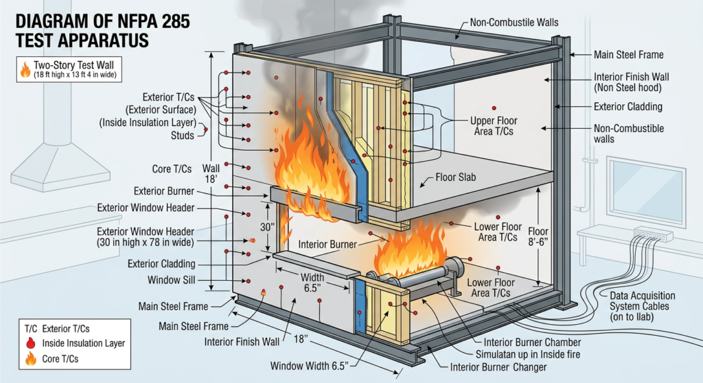
    NFPA 285 test apparatus showing two-story wall assembly with window burner

    ◆ Section 3: NFPA 285 — The Assembly Test

    NFPA 285 evaluates the fire propagation characteristics of exterior wall assemblies containing combustible components.

    A. What NFPA 285 Tests

    The test is run on a two-story mock-up. A room fire is allowed to reach flashover and break out through a window opening, with a burner at the window exposing the exterior wall. Flame propagation is assessed:

    • Vertically and horizontally across the exterior surface
    • Within the assembly layers (through insulation, WRB, and cladding)
    • Through air gaps and cavities
    • From floor to floor

    The test is pass/fail. Criteria include limits on how far flames spread vertically and laterally from the window opening, flames entering the second-story room, and temperature limits at thermocouples within the assembly. The test also generates extensive temperature data. Refer to the standard for the exact criteria.

    B. When NFPA 285 Is Required

    The IBC triggers NFPA 285 testing for exterior walls of Type I, II, III, or IV construction that are greater than 40 feet in height above grade plane and contain combustible components. The trigger applies when the exterior wall covering, insulation, or water-resistive barrier is combustible.

    Common triggers include:

    • Foam plastic insulation in the exterior wall
    • Combustible water-resistive barriers
    • Metal composite material (MCM) systems with combustible cores
    • Exterior wall veneers or panels using combustible adhesives or cores (check the language in your adopted edition)

    C. Exceptions

    Exceptions exist where the combustible component is limited. For example, walls where the WRB is the only combustible component and the exterior covering is brick, concrete, stone, terra cotta, stucco, or steel may be exempt. The WRB must also meet heat release limits under ASTM E1354 testing to use the exception. Typical limits are on the order of 150 kW/m² peak heat release rate, 20 MJ/m² total heat release, and 18 MJ/kg effective heat of combustion, but verify the exact values and conditions in your adopted edition.

    Key point: NFPA 285 is not required for every curtain wall. It is required when the wall assembly contains combustible components and exceeds the height threshold. A curtain wall with noncombustible cladding and no combustible insulation or WRB may not trigger the requirement. Sprinklers do not remove the requirement.

    Pro Tip: Recent code editions allow compliance by an approved analysis based on a tested assembly. This lets subject-matter experts evaluate modifications to tested assemblies through fire science analysis, submitted to the AHJ for approval.

    ◆ Section 4: ASTM E2307 — Perimeter Fire Barriers

    The perimeter fire barrier is the seal between the exterior wall assembly and the floor slab. It prevents fire from spreading from one floor to the next through the void at the floor/wall intersection.

    A. What ASTM E2307 Tests

    ASTM E2307 measures the perimeter fire barrier’s ability to maintain a seal to prevent fire spread during the deflection and deformation of the exterior wall assembly and floor assembly during a fire test. The test uses an intermediate-scale, multi-story apparatus and subjects the perimeter joint to:

    • Fire exposure from an interior compartment fire
    • Flame plume from a window burner below
    • Deflection and deformation of the wall and slab as the fire develops

    The result is reported as an F rating, in hours, based on the barrier’s ability to resist the passage of flame.

    B. Test Conditions

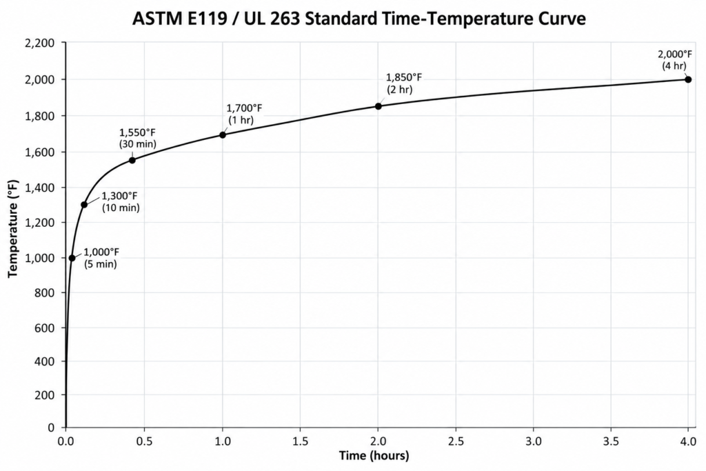
    The fire exposure conditions are those specified by the test method for the first 30 minutes, then conform to the ASTM E119 time-temperature curve for the remainder of the test.

    C. What ASTM E2307 Does Not Measure

    The test does not provide quantitative information about:

    • Smoke or gas leakage through the perimeter fire barrier
    • Flame spread over the exterior face of the assembly
    • Spread of flame within the combustible core of sandwich panels
    • Spread of flame over the interior surface

    These are addressed by other test methods, notably NFPA 285 for exterior flame propagation.

    D. E2307 Versus Joint System Tests

    Perimeter fire barriers are not the same as joint systems tested to UL 2079 or ASTM E1966. Joint systems address movement joints within rated assemblies. The perimeter barrier at an exterior curtain wall is evaluated to E2307 because the exterior fire exposure and wall deflection are different. Do not substitute one for the other.

    Key point: ASTM E2307 and NFPA 285 are complementary. ASTM E2307 evaluates the perimeter joint; NFPA 285 evaluates the entire wall assembly including vertical and lateral flame spread.

    Pro Tip: The perimeter fire barrier is a critical detail that is often value-engineered out or improperly installed. It must be specified, inspected, and maintained.

    ◆ Section 5: Perimeter Fire Containment in the IBC (§715.4)

    The IBC requires voids at the intersection of an exterior curtain wall assembly and a fire-resistance-rated floor or floor/ceiling assembly to be sealed with an approved system. The system must be tested to ASTM E2307 and provide an F rating for a period not less than the fire-resistance rating of the floor assembly. This is the code provision that makes E2307 mandatory, and it is distinct from the NFPA 285 trigger.

    Key point: E2307 produces an F rating only. It does not produce an L (leakage) rating, so smoke sealing at the perimeter requires its own specification and detail.

    Pro Tip: Check your adopted edition for exceptions and for any separate smoke-sealing language. Do not assume the F rating alone addresses smoke.

    ◆ Section 6: Spandrels and Vertical Separation of Openings (§705.8.5)

    Windows stacked vertically are a fire path through the façade even with a perfect perimeter barrier. For buildings of more than three stories, the IBC generally separates vertically aligned openings that are close horizontally. The separation is a spandrel of at least 3 feet with a 1-hour fire-resistance rating, or a flame barrier projecting at least 30 inches from the wall. Buildings fully protected by an automatic sprinkler system under the applicable IBC provisions are generally exempt, but verify the exceptions and the horizontal distance criteria in your adopted edition.

    Key point: Spandrel areas are where perimeter safing, backpan insulation, mullion fireblocking, and the spandrel panel itself all meet. Coordinate them in a single detail rather than as separate trades.

    ◆ Section 7: Perimeter Barrier Details That Fail in the Field

    The tested system is a specific combination of products, thicknesses, compression, and gap widths. Failures in the field commonly come from:

    • Mineral wool safing that is not compressed to the tested percentage or not sized to the actual slab-edge gap
    • Missing or incorrect mechanical support, such as impaling clips or angles called for in the listing
    • Missing or wrong sealant or coating at the face, or a smoke seal that is omitted
    • Unsealed mullion cavities, gaps at columns, and slab-edge irregularities
    • Gaps wider than the tested range once building movement is accounted for
    • Substituted products that void the listing

    Key point: If the field condition is not covered by the listing, it is not a tested system.

    ◆ Section 8: Combustible Components in Curtain Walls

    Many modern curtain walls contain combustible components that must be evaluated as part of the assembly.

    A. Foam Plastic Insulation

    Foam plastic insulation is common in curtain wall systems for thermal performance. The IBC requires foam plastic in exterior walls of Type I–IV construction to comply with Section 2603.5, which includes:

    • A thermal barrier separating foam from the building interior (unless special approval)
    • Potential heat limits (not exceeding that of the tested assembly)
    • Flame spread and smoke-developed indices of 25/450 or less
    • NFPA 285 compliance for vertical and lateral fire propagation

    B. Aluminum Composite Materials (ACM/MCM)

    ACM panels with combustible cores (often polyethylene) have been implicated in major façade fires. The IBC requires MCM systems containing foam plastic insulation to comply with Section 2603, including NFPA 285 testing. MCM also has its own provisions in Chapter 14.

    C. Water-Resistive Barriers (WRB)

    Combustible WRBs are a common NFPA 285 trigger. NFPA 285 is required when the WRB is combustible, unless the exception applies (WRB is the only combustible component with an approved noncombustible cladding).

    D. Combustible Adhesives and Cores

    Some veneers and panels use combustible adhesives to laminate a metal core with noncombustible facings. Check whether your adopted edition requires these systems to comply with NFPA 285.

    Key point: The trend in code development has been to expand NFPA 285 triggers as new combustible components are introduced.

    Pro Tip: When reviewing curtain wall submittals, verify every combustible component and whether it triggers NFPA 285. A single combustible WRB can trigger the requirement even if the cladding is noncombustible.

    ◆ Section 9: Vertical Fire Spread and the Stack Effect

    Curtain walls can contribute to vertical fire spread through three mechanisms:

    A. Combustible Core Spread

    In ACM panels with combustible cores, fire can spread within the panel core from floor to floor, bypassing the perimeter fire barrier.

    B. Cavity and Air Gap Spread

    Air gaps and cavities within the curtain wall assembly can act as chimneys, drawing flames and hot gases upward. NFPA 285 specifically evaluates flame propagation through air gaps and cavities. At Grenfell Tower, the ventilated cavity and the combustible insulation worked together with the burning panels to accelerate spread.

    C. Window-to-Window Spread

    Flames leaving a window can lap up the exterior and enter the window above, especially when glass fails. This is addressed by spandrel and vertical separation provisions and by sprinklers, not by NFPA 285 or E2307 alone.

    Key point: The perimeter fire barrier prevents spread through the floor/wall joint, but it does not prevent spread through the curtain wall assembly itself or between windows. NFPA 285 (assembly), ASTM E2307 (perimeter joint), and the IBC spandrel provisions are all needed.

    ◆ Section 10: Glazing and Vision Glass

    Windows are where an interior fire exits the building. Glass fracture and fall-out expose the floor above to flame and can allow the fire to extend vertically even when the cladding is noncombustible.

    • Annealed and some tempered glass can crack and fall out early; heat-strengthened and laminated glass may behave differently.
    • Aluminum mullions soften at relatively low temperatures, which allows frame deformation and glass loss.
    • Sprinklers near glazing can reduce glass fracture and flame exposure to the floor above.
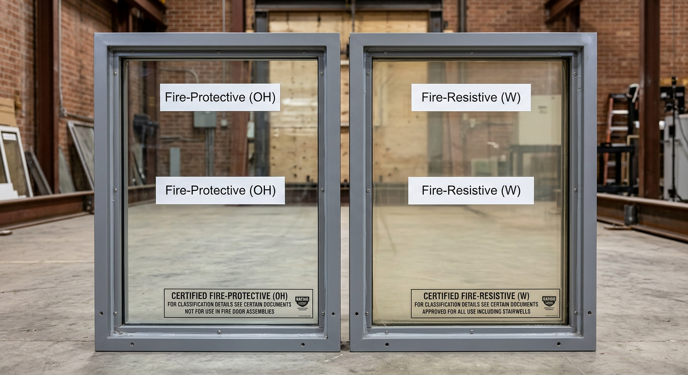
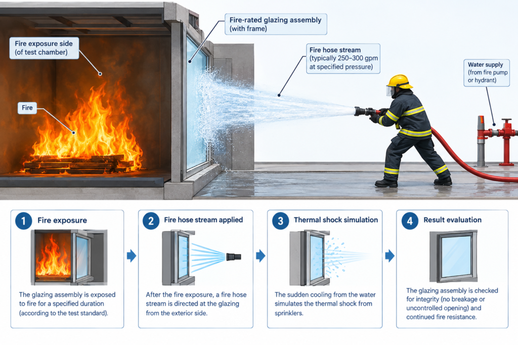
    • Fire-rated glazing is used where the IBC requires rated openings or rated spandrels.

    Key Article: Fire-Rated Glazing: Types, Ratings, and Applications

    Pro Tip: A rating on the glass is not a rating on the frame or the joint to the slab. Evaluate the complete system.

    ◆ Section 11: Design Variations, Listings, and Engineering Judgments

    Tested assemblies are narrow. Changes to insulation type or thickness, panel size, attachment, cavity depth, or WRB can fall outside the test. Compliance options typically include:

    • A direct test of the exact assembly
    • A third-party listed assembly
    • An approved engineering analysis or Engineering Judgment (EJ) based on tested assemblies

    For any variation, document the reasoning, submit it to the AHJ for approval, and keep the record in the project file.

    Key point: An EJ is only as strong as the test data and expertise behind it. Early AHJ engagement avoids late rejection.

    ◆ Section 12: Case Studies

    A. First Interstate Bank Building, Los Angeles (1988)

    This unsprinklered high-rise fire burned through several floors, spreading largely through the exterior. Glass broke and flames moved from window to window while fire also extended through the curtain wall. The case predates Grenfell and shows that perimeter joint performance, glass failure, and the lack of sprinklers drive vertical spread, not only combustible cladding.

    B. Grenfell Tower, London (2017)

    The Grenfell Tower fire in London on June 14, 2017, killed 72 people and led to a fundamental reassessment of façade fire safety worldwide.

    What happened. The fire broke out in a fourth-floor apartment and spread rapidly up the building’s exterior. The cladding consisted of aluminum composite panels with a combustible polyethylene core, combined with combustible foam insulation and a ventilated cavity.

    The inquiry findings. The Phase 2 report, published in September 2024, concluded that the fire resulted from decades of failure by government and industry bodies to address the danger of combustible materials in the external walls of high-rise residential buildings. The inquiry concluded that all deaths were avoidable.

    Regulatory response. The fire led to:

    • A ban in England on combustible materials in the external walls of new high-rise residential buildings above a set height (Scotland and Wales have separate rules)
    • Enhanced oversight through the Building Safety Act 2022 and the Building Safety Regulator
    • Global reevaluation of NFPA 285 compliance and façade fire safety

    C. Other Façade Fires

    Lacrosse Building (Melbourne, 2014) and The Address Downtown (Dubai, 2015) are widely cited examples of fires spreading over combustible panels and cladding.

    Key point: Grenfell demonstrated that the consequences of non-compliant or inadequately tested façade systems are catastrophic. First Interstate demonstrated that even without combustible cladding, exterior and perimeter weaknesses can carry fire upward.

    ◆ Section 13: Construction, Inspection, and Maintenance

    • IBC Chapter 17 special inspection of fire-resistant joints and penetrations. Verify the section number and scope in your edition.
    • Inspect and photograph the perimeter barrier before it is concealed by ceilings, cladding, or other trades.
    • Control fire risk during construction, when combustible façade materials may be exposed (see NFPA 241).
    • Re-inspect after alterations. New penetrations, replaced panels, or added insulation can break compliance.
    • Keep the tested assembly documentation, listings, and submittals as part of the building records.

    ◆ Section 14: Existing Buildings and Retrofit

    Re-cladding, façade upgrades, and adding insulation can trigger NFPA 285 even if the original wall did not. Treat the new work as new construction and check the applicable existing-building code. For older high-rises, a façade fire audit is advisable, especially where ACM, foam insulation, or unlisted perimeter joints are suspected.

    ◆ Section 15: International Comparison

    Many countries use different tests. The UK uses BS 8414 with BR 135 for external fire spread, Canada uses CAN/ULC S134, and Europe uses EN 13501-1 reaction-to-fire classes. They are not interchangeable with NFPA 285. Global projects should confirm which test the local authority accepts.

    ◆ Section 16: Design Checklist for Curtain Wall Fire Safety

    Item Status Notes
    Height threshold confirmed ☐ NFPA 285 triggered at >40 ft for Type I–IV construction with combustible components
    Combustible components identified ☐ WRB, insulation, cladding core, adhesives
    NFPA 285 compliance determined ☐ Direct test, listed assembly, or engineering analysis
    ASTM E2307 perimeter barrier specified ☐ Tested system for floor/wall joint
    IBC §715.4 perimeter containment ☐ F rating not less than floor rating
    Spandrel / vertical separation of openings (§705.8.5) ☐ Spandrel or flame barrier, or sprinkler exception
    Foam plastic insulation compliant ☐ IBC §2603.5: thermal barrier, potential heat, NFPA 285
    MCM/ACM systems reviewed ☐ Core combustibility; NFPA 285 compliance
    Perimeter fire barrier detailed ☐ Mineral wool, sealant, and attachment per listing
    Mullion cavity fireblocking and spandrel safing ☐ IBC §718 and the tested system
    Glazing fracture behavior and sprinkler coordination ☐ Window-to-window spread
    Engineering Judgments documented ☐ If used for design variations
    Special inspection records for perimeter joints ☐ IBC Chapter 17
    AHJ coordination ☐ Early engagement on compliance path

    ◆ Section 17: Common Mistakes and How to Avoid Them

    Mistake Why It’s a Problem How to Fix
    Assuming NFPA 285 applies only to foam plastic Combustible WRBs and adhesives also trigger Identify all combustible components
    Confusing NFPA 285 with ASTM E2307 Different tests, different purposes Specify both where required
    Using a UL 2079 joint system as a perimeter barrier Different test and exposure Specify an E2307 tested system
    Using ASTM E84 Class A as sole basis E84 is not an assembly test Require NFPA 285 compliance for the assembly
    Assuming sprinklers remove the need for NFPA 285 The trigger is construction type, height, and combustibles Evaluate the trigger independently of sprinklers
    Omitting perimeter fire barrier Fire can spread through floor/wall joint Specify ASTM E2307 tested system
    Value-engineering out the perimeter barrier Code violation; fire spread path Include in base scope; inspect installation
    Substituting safing or sealant on site Voids the listing Require the listed system and verify in the field
    No engineering analysis for design changes Compliance unverifiable Document EJ and submit to AHJ
    Ignoring combustible core in MCM Vertical fire spread path Verify core combustibility and NFPA 285 compliance
    Not coordinating with AHJ Delays; rejected submittals Early engagement on compliance path

    ◆ Section 18: Conclusion

    Curtain walls present unique fire safety challenges because they are non-structural cladding systems that often contain combustible components. NFPA 285 evaluates the entire wall assembly for vertical and lateral flame propagation. ASTM E2307 evaluates the perimeter fire barrier at the floor/wall intersection, and the IBC requires it. Spandrels, glazing, and fireblocking complete the strategy. All are needed.

    The First Interstate and Grenfell fires showed two different ways façades fail: through exterior and perimeter weaknesses, and through combustible cladding that was never properly tested as an assembly. Façade fire safety cannot be assumed; it must be tested, detailed, inspected, and maintained.

    Key Takeaways:

    • NFPA 285 is an assembly test, not a material test; it evaluates the entire exterior wall system.
    • NFPA 285 is triggered for Type I–IV construction over 40 ft with combustible WRBs, insulation, or cladding.
    • ASTM E2307 evaluates the perimeter fire barrier’s ability to maintain a seal during fire and movement, and IBC §715.4 makes it mandatory with an F rating at least equal to the floor rating.
    • E2307 does not address smoke leakage; smoke sealing needs its own specification.
    • Spandrels, glass failure, and mullion cavities are fire paths even when the cladding is noncombustible.
    • Combustible components (WRBs, foam insulation, MCM cores, and adhesives) trigger NFPA 285 requirements.
    • Tested assemblies are narrow; design variations need listings or documented, AHJ-approved engineering analysis.
    • Inspection during construction and re-inspection after alterations are essential to keep the system compliant.
    • First Interstate shows fire spread without combustible cladding; Grenfell shows the catastrophic result of untested combustible façades.

    Take Action Today:

    • Determine whether your building triggers NFPA 285 (height and combustible components).
    • Identify all combustible components in the curtain wall assembly.
    • Verify NFPA 285 compliance through direct test, listing, or engineering analysis.
    • Specify an ASTM E2307 tested perimeter fire barrier with the required F rating.
    • Detail spandrels, safing, mullion fireblocking, and smoke sealing together.
    • Verify foam plastic insulation compliance with IBC §2603.5.
    • Document any Engineering Judgments and submit to the AHJ.
    • Arrange special inspections and photograph the perimeter barrier before concealment.
    • Coordinate with the AHJ early on the compliance path.

    Continue Reading from Our Series:

  • Fire-Rated Glazing: Types, Ratings, and Applications

    Fire-Rated Glazing: Types, Ratings, and Applications

    IMPORTANT DISCLAIMER: This guide references the International Building Code (IBC), Chapter 7 (Fire and Smoke Protection Features), specifically Section 716 (Opening Protectives), Table 716.1(1) (Markings) and Table 716.1(2) (Opening Fire Protection Assemblies by Wall Rating); IBC Section 2406 (Safety Glazing); NFPA 80, Standard for Fire Doors and Other Opening Protectives; NFPA 252, Standard Methods of Fire Tests of Door Assemblies; NFPA 257, Standard on Fire Test for Window and Glass Block Assemblies; UL 9, Fire Tests of Window Assemblies; UL 10B and UL 10C (door assembly tests); UL 1784 (air leakage tests of door assemblies); ASTM E119, Standard Test Methods for Fire Tests of Building Construction and Materials; UL 263; 16 CFR 1201 (CPSC safety glazing); and ANSI Z97.1. These codes and standards vary by edition and are frequently amended by state and local jurisdictions. IBC Section 716 was Section 715 in the 2009 edition and earlier. Verify section numbers against your AHJ-adopted edition. Local amendments and the edition adopted by your Authority Having Jurisdiction (AHJ) always control. This guide is a starting point only. Always verify the specific requirements applicable to your project with your local AHJ.

    Fire-rated glazing is one of the most misunderstood products in commercial construction. Unlike a fire door, which is a complete assembly with a single rating, glazing performance depends on two separate and independent characteristics: the ability to block flames and smoke, and the ability to block heat. A product can do the first without doing the second, and that distinction determines where it can be used.

    The IBC and the test standards recognize two categories of fire-rated glazing: fire-protective (also called fire-protection-rated) and fire-resistive (fire-resistance-rated). Each has its own test standards, its own labeling system, and its own application limits. Confusing them, or relying on the fire endurance rating alone, leads to noncompliant installations that may pass a plan review but fail in a fire or at inspection.

    This article covers the types of fire-rated glazing, the testing standards that govern them, the hose stream requirement, size and application limits, labeling, impact safety, frames and installation, and common field problems.

    ◆ Section 1: Why Glazing Ratings Are Different

    A fire-rated wall is tested as a complete assembly under ASTM E119. It has one rating, and it either meets the acceptance criteria or it does not. Glazing is different because it is tested in different ways depending on what it must accomplish: as a window, as part of a door, or as part of a wall.

    Characteristic Fire-Protective Glazing Fire-Resistive Glazing
    Blocks flames and smoke Yes Yes
    Blocks radiant and conductive heat No Yes
    Test standard (windows, sidelights, transoms) NFPA 257 or UL 9 ASTM E119 or UL 263
    Test standard (as part of a door) NFPA 252, UL 10B or UL 10C ASTM E119 or UL 263, plus NFPA 252, UL 10B or UL 10C
    Label marking OH-XXX (windows); D-H-… (doors) W-XXX; D-H-W-XXX (doors)
    Typical rating range 20 to 180 minutes (varies by product and application) 20 to 120 minutes typical; some products listed higher
    Area limit in fire windows 25% of the area of the common wall with any room Not subject to the 25% limit
    Where used Doors, sidelights, transoms, fire windows in walls where windows are permitted Fire barriers, fire partitions, shafts, exit enclosures and corridors where heat blocking or a higher rating is required

    Note: Sidelights and transoms are evaluated as fire window assemblies (NFPA 257 or UL 9), not as part of the door leaf. Many products also carry a door listing (D-H-OH-XXX) so they can be used in either role.

    Key point: Fire-protective glazing stops flames and smoke. Fire-resistive glazing does that and also blocks heat. A wall that must maintain a tenable environment on the non-fire side, or that is rated beyond what fire windows are allowed in, needs fire-resistive glazing, not fire-protective.

    Key Article: Article 131 — Fire-Resistance-Rated Assemblies and UL Listings

    Pro Tip: The fire endurance rating alone does not tell you whether a product is fire-protective or fire-resistive. A “60-minute” fire-protective glazing and a “60-minute” fire-resistive glazing are not interchangeable. Read the label and the listing.

    ◆ Section 2: Fire-Protective Glazing

    Fire-protective glazing defends against the spread of flames and smoke for its designated fire rating. It does not block the transfer of radiant and conductive heat.

    A. Test Standards

    Standard Application
    NFPA 257 / UL 9 Fire window assemblies (windows, and sidelights and transoms where they are treated as windows)
    NFPA 252 Fire door assemblies (glazing as part of the door)
    UL 10C Fire door assemblies, positive pressure test
    UL 10B Fire door assemblies, neutral pressure test (the IBC calls for positive pressure testing of doors, so check which method your adopted edition accepts)

    B. Types of Fire-Protective Glazing

    Type Typical Rating Appearance Typical Applications
    Specialty tempered 20 minutes Optically clear, no wires 20-minute doors up to the maximum size tested
    Specialty tempered, heat reflective 20–60 minutes Clear, no wires 20–45 minute doors; 60-minute doors up to 100 sq in where limited; 45-minute sidelights and transoms
    Specialty fire-protective 90 minutes Clear, no wires 90-minute doors, generally limited to 100 sq in
    Traditional wired glass 20–90 minutes Annealed glass with embedded wire Fire windows and transoms in non-hazardous locations; not a safety glazing product (see Section 8)
    Safety wired glass 20–90 minutes Wired glass with safety film 20–45 minute doors; 60–90 minute doors up to 100 sq in
    Filmed safety ceramic 20–180 minutes (per listing) Wire-free, slight tint 20–45 minute doors; 60–90 minute doors up to 100 sq in; higher ratings only in applications the code allows
    Laminated safety ceramic 20–180 minutes (per listing) Wire-free, slight tint Same as filmed ceramic

    Key point: A product may be listed for a rating or size that the IBC does not permit in a given application. Listing sets the ceiling; the code decides whether you may use it.

    C. Area and Size Limits

    Fire-protective glazing is limited by area in fire window assemblies and by size in doors.

    • Fire windows. The total area of fire window assemblies is limited to 25 percent of the area of the common wall with any room (see the notes to Table 716.1(2)). This limit applies to fire windows, not to the vision panel in a door.
    • Door vision panels. Limits depend on the door rating. See Section 5.
    • Where fire windows are not permitted. Table 716.1(2) does not permit fire windows (fire-protective windows) in fire walls, in fire barriers rated more than 1 hour, or in shaft and exit enclosure walls. Fire-resistive glazing is the option in those walls.

    Key point: The 25% limit exists because fire-protective glazing lets radiant heat through. The practical effect is that a mostly-glass wall would not provide the protection of a solid rated wall.

    Pro Tip: For 60- and 90-minute doors in exit enclosures and exit passageways, fire-protective vision panels are limited to 100 square inches whether or not the building is fully sprinklered.

    ◆ Section 3: Fire-Resistive Glazing

    Fire-resistive glazing provides the same defense against flames and smoke as fire-protective glazing, but it also blocks the transfer of radiant and conductive heat. It is tested as a wall assembly, so the label “W” means the glazing meets the wall-assembly criteria of ASTM E119 or UL 263.

    A. Test Standards

    • ASTM E119, Standard Test Methods for Fire Tests of Building Construction and Materials
    • UL 263, Fire Tests of Building Construction and Materials
    • As part of a door assembly, also NFPA 252, UL 10B, or UL 10C
    • Some applications and listings also include the hose stream test, which appears in the label (see Sections 4 and 6)

    B. Where Fire-Resistive Glazing Is Used

    Fire-resistive glazing is suitable where the code requires an assembly with a fire-resistance rating to enclose a space, and where fire windows are not permitted. Examples:

    • Walls requiring a 1-hour or greater rating where fire windows are not allowed or the 25% limit would be exceeded
    • Exit enclosure (stair) and shaft walls where a glazed wall lite is wanted
    • Rated exit access corridors
    • Fire barriers and fire partitions that need transparency

    Because fire-resistive glazing blocks heat, it is not subject to the 25 percent area limit for fire windows.

    C. Size Limits

    Fire-resistance-rated glazing tested to ASTM E119 or UL 263 may be used in fire door assemblies up to the maximum size tested and in accordance with its listing. The 100 sq in limit that applies to fire-protective glazing in certain doors does not apply to it.

    Key point: Fire-resistive glazing is the option when the code requires both separation and heat protection, or when the wall rating is too high for fire windows.

    Pro Tip: Fire-resistive glazing is typically thick (multi-laminated, or with intumescent interlayers or gel) and carries a W marking on the label. Fire-protective glazing is typically thin and carries an OH marking (for windows) or D-H markings (for doors).

    Diagram of hose stream test for fire-rated glazing showing water spray on heated assembly

    ◆ Section 4: The Hose Stream Requirement

    The hose stream test is one of the most misunderstood aspects of fire-rated glazing.

    A. What the Hose Stream Test Is

    Immediately after the fire exposure, the heated assembly is sprayed with water from a hose stream. This tests impact, erosion, and thermal shock, simulating the effect of sprinkler or fire department water on hot glass. In the U.S., the hose stream test is a pass/fail requirement for assemblies rated 45 minutes and longer. If the glass or framing fails, flames and smoke can spread. To earn a hose stream designation, the glazing and framing must remain in place and not break away.

    B. The Hose Stream and Fire Door Assemblies

    Condition Hose Stream Required?
    20-minute door assemblies in corridor walls or smoke barriers No. Tested per NFPA 252 or UL 10C without hose stream
    20-minute doors in other fire partitions (0.5-hour rating) Yes. Tested with hose stream
    45-minute and longer doors Yes. Tested with hose stream
    Sidelights and transoms in those same corridor and smoke barrier walls Yes. They are treated as fire window assemblies, tested per NFPA 257 or UL 9, including hose stream

    The corridor exemption applies to the door assembly only. Sidelights and transoms around that door are windows, not doors, and do not share the exemption.

    C. Label Markings

    Marking Meaning
    H Glazing meets the hose stream requirements of NFPA 252, UL 10B, or UL 10C
    OH Glazing meets the fire protection and hose stream requirements of NFPA 257 or UL 9 (fire window assemblies)
    NH Older marking for glazing not meeting hose stream. You may still see it on older products; check the status in your adopted edition

    Key point: The hose stream requirement is not universal. The code relaxes it for 20-minute door assemblies in corridors and smoke barriers, but not for the sidelights and transoms in the same wall.

    Pro Tip: Glazing marked as meeting hose stream (H) may be used where hose stream is not required. The reverse is not true.

    ◆ Section 5: Size Limits in Door Vision Panels

    The IBC limits the size of glazing in fire door vision panels based on the glazing type and the door rating.

    A. Fire-Protective Glazing in Doors

    Door Rating Fire-Protective Glazing Size
    20 minutes Up to the maximum size tested
    45 minutes Up to the maximum size tested
    60 and 90 minutes 100 sq in maximum in exit enclosures and exit passageways, whether or not the building is sprinklered; elsewhere per §716 and the listing
    180 minutes Generally not permitted. Confirm the limited exceptions (such as certain horizontal exit doors) in your adopted edition

    B. Fire-Resistive Glazing in Doors

    Fire-resistance-rated glazing larger than 100 sq in is permitted in fire doors when it is tested to ASTM E119 or UL 263 and to NFPA 252, UL 10B, or UL 10C, up to the maximum size tested and in accordance with its listing.

    C. Sidelights and Transoms

    Glazing in sidelights and transoms in corridors and smoke barriers is tested per NFPA 257 or UL 9, including hose stream. Fire-protective glazing is permitted only where fire windows are permitted for the wall rating (and within the 25% limit). Where the wall rating is too high for fire windows, such as fire barriers rated over 1 hour, fire-resistance-rated glazing is required.

    Key point: The 100 sq in limit is a limit on fire-protective glazing in 60- and 90-minute doors in exit enclosures and exit passageways. Fire-resistive glazing tested as part of the door is not held to it.

    Pro Tip: When reviewing plans, check the door rating before checking vision panel size. A large lite in a 20-minute corridor door may be fine; the same lite in a 90-minute stair door with fire-protective glazing is not.

    ◆ Section 6: Labeling and Identification

    Every piece of fire-rated glazing must carry a permanent label showing the manufacturer, the test standard or listing, and the rating marking. The marking system is defined in IBC Table 716.1(1).

    A. Marking Key

    Symbol Meaning
    OH Opening protective: meets the fire window requirements of NFPA 257 or UL 9, including hose stream
    D Glazing tested as part of a door assembly (NFPA 252, UL 10B or UL 10C)
    H Meets the hose stream requirement
    T Meets the temperature rise criteria (450°F rise at 30 minutes) used for certain exit enclosure and exit passageway doors
    W Meets the wall assembly criteria of ASTM E119 or UL 263 (fire-resistive glazing)
    XXX Rating period in minutes

    B. Fire-Protective Glazing Markings

    • OH-XXX: fire window assemblies (tested to NFPA 257 or UL 9, including hose stream)
    • D-H-OH-XXX: glazing used in sidelights and transoms in certain corridor walls and smoke barriers that must also be tested to NFPA 252 because they are part of a door assembly
    • D-H-XXX: glazing in fire door assemblies tested with hose stream
    • D-H-T-XXX: glazing in doors that also meets the temperature rise criteria

    C. Fire-Resistive Glazing Markings

    • W-XXX: the glazing meets the wall assembly criteria of ASTM E119 or UL 263 for the rating period shown
    • D-H-W-XXX: fire-resistive glazing in a door assembly tested with hose stream. For example, D-H-W-90 is a 90-minute fire-resistive glazing in a door assembly

    Some glazing may carry an S marking when it is part of a smoke and draft control assembly (see Section 9).

    D. Label Requirements

    The label must be issued by an approved agency and permanently affixed to the glazing. It identifies the manufacturer, the test standard, and the marking.

    Key point: The label is the compliance document. A missing, painted-over, or damaged label makes an otherwise compliant installation unverifiable. Inspectors check labels during plan review and field inspection.

    Pro Tip: A quick way to read a marking: OH = opening protective (fire window), D = door, H = hose stream, T = temperature rise, W = wall (fire-resistive), XXX = minutes.

    ◆ Section 7: Common Applications

    A. Corridors

    Corridor ratings are set by IBC Table 1020.2. In many sprinklered buildings the corridor rating is 0 hour, so rated glazing is not needed at all. Where a corridor wall is rated (typically 1 hour, or 0.5 hour in some cases), Table 716.1(2) governs:

    • Doors are typically 20 minutes, with the corridor exemption from the hose stream test described in Section 4.
    • Sidelights, transoms and windows must be fire windows (tested to NFPA 257 or UL 9, with hose stream) within the permitted rating and the 25% area limit, or fire-resistive glazing.

    Fire-resistive glazing is a design choice where a larger glazed area or greater visual openness is wanted, or where the wall rating is too high for fire windows. It is not a general requirement for exit access corridors.

    B. Stairwells and Exit Enclosures

    Exit enclosures are rated fire barriers (1 hour or 2 hours depending on the number of stories connected). In these walls:

    • Doors: a 60-minute or 90-minute door may have a fire-protective vision panel, limited to 100 sq in. Larger vision panels or a more open look need fire-resistive glazing tested as part of the door.
    • Walls: fire windows (fire-protective glazing) are not permitted in exit enclosure walls. A glazed wall lite in a stair enclosure must be fire-resistive glazing (W).
    • Temperature rise: in buildings that are not sprinklered throughout, doors in exit enclosures and exit passageways must also meet the temperature rise (T) criteria. Radiant heat on the egress path is the reason.

    C. Fire Barriers, Fire Partitions and Shafts

    • Fire barriers rated 1 hour or less may use fire windows within the Table 716.1(2) limits and the 25% area limit.
    • Fire walls and fire barriers rated more than 1 hour do not permit fire windows. Use fire-resistive glazing.
    • In fire doors in fire walls and 3-hour barriers, fire-protective vision panels are generally not permitted, with limited exceptions such as certain horizontal exit doors. Confirm in your adopted edition.

    D. Exterior Walls

    Fire windows (OH) may be used in exterior walls where opening protectives are required. Exterior wall openings are also limited by fire separation distance and maximum area of openings under IBC Section 705.8, and fire-resistive glazing may be used where the wall itself must be rated.

    E. Atriums and Large Spaces

    Atrium separation under IBC Section 404.6 may be provided by a 1-hour fire barrier or, in some cases, by glass walls with sprinkler protection. Fire-resistive glazing is one way to build a transparent fire barrier that keeps the visual connection between floors. Sprinkler-based glass walls rely on the sprinkler design, so coordinate with the fire protection engineer.

    Key point: The application determines the glazing type. A stair enclosure wall lite needs heat blocking. A corridor vision panel may need nothing, or only a fire window, depending on the wall rating.

    ◆ Section 8: Impact Safety and Safety Glazing

    Fire rating is only half of the compliance picture. Glazing in doors, sidelights near doors, and other hazardous locations must also meet the safety glazing requirements of IBC Section 2406 and the impact standards 16 CFR 1201 (CPSC) or ANSI Z97.1.

    • Traditional wired glass does not meet the impact safety requirements for hazardous locations. It is limited to locations where safety glazing is not required, and some jurisdictions (for example, for school buildings) restrict it further.
    • Safety wired glass and specialty tempered, ceramic and laminated products are available with impact safety ratings and are the usual choice for doors, sidelights, and glazing near floor level.
    • Fire-resistive glazing assemblies must also be checked for impact safety category where they are in hazardous locations.

    Key point: A product can be fully compliant for fire and noncompliant for impact. Check both listings.

    Pro Tip: Ask for two documents for every glazing product: the fire listing and the safety glazing certificate.

    ◆ Section 9: Frames, Systems and Installation

    Fire-rated glazing is not rated alone. The rating belongs to a tested system: glass, frame, glazing bead, tape, gasket, and anchorage as listed.

    • Use the listed frame. Fire-rated glass in a frame that is not listed for it voids the rating. Fire-resistive glazing in particular is often tested in specific frame profiles.
    • No field modification. Do not cut, drill, or re-notch labeled glass, or change beads, tapes, or sealants without a listing that allows it.
    • Install per NFPA 80 for doors and opening protectives, and per the manufacturer’s installation instructions and listing.
    • Smoke and draft control. Where the door or window must also resist smoke passage (for example, smoke barriers), the assembly is tested per UL 1784 and carries an S marking. Make sure the glazing system is part of that listing.
    • Inspection. NFPA 80 requires fire door assemblies to be inspected and tested after installation and at least annually. Include glazing, labels, and frames in that review: look for cracks, missing beads, painted labels, and film or signage applied over the glass.

    Key point: If the frame, beads, or installation do not match the listing, the glass rating does not apply.

    ◆ Section 10: Existing Buildings and Replacement Glass

    • Legacy wired glass. Existing buildings often have wired glass that is still permitted where it was legally installed. Replacement is often required where it is in a hazardous location or when the area is altered. Check the International Existing Building Code and local rules.
    • Unlabeled glass. Without a label, the glass cannot be treated as rated. It must be replaced with labeled product or verified by the AHJ.
    • Broken glass. Replacement glass must match the original listing, including the rating, the frame system, and the size limits. A clear replacement pane that looks the same is not enough.
    • Films and coatings. Do not apply film to rated glass unless the manufacturer’s listing allows it.

    ◆ Section 11: Selection and Cost Considerations

    Fire-resistive systems are heavier, thicker, and several times more expensive than fire-protective glazing in many cases, and they need specific frames. Fire-protective glazing is lighter and cheaper, but is limited by area, size, and rating.

    Factor Fire-Protective Fire-Resistive
    Relative cost Lower Higher
    Weight and thickness Thin, lighter Thick, heavier
    Frames Standard listed fire frames Often specific listed frames
    Area limits 25% in fire windows None from the 25% rule
    Best for Door vision panels, limited sidelights and transoms, fire windows in lower-rated walls Walls over 1 hour, stair enclosures, large glazed walls, heat protection

    Pro Tip: Decide early. Changing from fire-protective to fire-resistive late in design often changes frame, wall thickness, and budget.

    ◆ Section 12: Design Checklist for Fire-Rated Glazing

    Item Status Notes
    Required wall rating determined ☐ Per IBC Table 716.1(2) and the wall rating tables
    Fire windows permitted for this wall? ☐ Not in fire walls, barriers over 1 hour, or exit enclosure and shaft walls
    Glazing type selected ☐ Fire-protective or fire-resistive
    Test standard confirmed ☐ NFPA 257/UL 9 (windows); NFPA 252/UL 10C (doors); ASTM E119/UL 263 (resistive)
    Hose stream requirement determined ☐ Based on door rating, wall type, and whether it is a door, sidelight or transom
    Door vision panel size verified ☐ By door rating and location; 100 sq in for 60/90-minute exit enclosure doors
    Window area limit verified ☐ 25% of common wall area for fire windows
    Temperature rise needed? ☐ Exit enclosure and exit passageway doors in non-sprinklered buildings
    Label marking confirmed ☐ OH-XXX, D-H-OH-XXX, D-H-T-XXX, W-XXX, D-H-W-XXX
    Impact safety confirmed ☐ IBC §2406; 16 CFR 1201 or ANSI Z97.1
    Frame listed for glazing ☐ Frame, beads, tape and anchorage as listed
    Smoke and draft control considered ☐ UL 1784 and S marking where required
    Installation per NFPA 80 ☐ For doors and opening protectives
    Label verification at closeout ☐ Permanent label present and legible

    ◆ Section 13: Common Mistakes and How to Avoid Them

    Mistake Why It’s a Problem How to Fix
    Assuming all “fire-rated glass” is the same Protective and resistive are different Verify label and test standard
    Using fire-protective glazing as a stair enclosure wall lite Fire windows are not permitted there and it does not block radiant heat Use fire-resistive glazing (W)
    Applying the 100 sq in limit to every door Not every door rating has that limit Check by door rating and location
    Allowing oversized fire-protective glazing in 60/90-minute exit enclosure doors Code violation Limit to 100 sq in or use fire-resistive glazing
    Ignoring the 25% limit for fire windows Code violation Calculate wall area and window area
    Assuming sidelights share the door’s hose stream exemption They are tested as windows Test per NFPA 257 or UL 9 with hose stream
    Rated glazing where the corridor is 0 hour Unneeded cost Check Table 1020.2 before specifying
    Using wired glass in hazardous locations Fails impact safety Use safety-rated glazing
    No permanent label on glazing Compliance cannot be verified Require labeled product; inspect at closeout
    Unlisted frame with listed glazing Assembly not listed Match frame and glazing listings
    Field cutting or modifying rated glass Voids the listing Order to size; no field modification
    Confusing T (temperature rise) with W (wall) Different performance criteria T = temperature rise for doors; W = fire-resistive glazing
    Replacing broken glass with a lookalike Rating lost Match the original listing

    ◆ Section 14: Conclusion

    Fire-rated glazing is not a single product. It is two distinct categories with different performance characteristics and different applications. Fire-protective glazing stops flames and smoke but does not block heat. Fire-resistive glazing does both, and is required where the code demands protection from radiant heat as well as fire separation, or where the wall rating is beyond what fire windows are allowed in.

    The hose stream requirement, size limits, labeling, impact safety, and installation all flow from that basic distinction. Getting the category right is the first step. Verifying the listing, the label, the frame, and the installation is the rest.

    Key Takeaways:

    • Fire-protective glazing blocks flames and smoke but not heat; it is tested to NFPA 257 or UL 9 as a window and NFPA 252 or UL 10C as part of a door.
    • Fire-resistive glazing blocks flames, smoke and heat; it is tested to ASTM E119 or UL 263.
    • Fire windows (fire-protective glazing) are limited to 25% of the common wall area and are not permitted in fire walls, barriers over 1 hour, or exit enclosure and shaft walls.
    • Hose stream is required for 45-minute and longer ratings and for 20-minute doors outside corridors and smoke barriers; 20-minute corridor door assemblies are tested without it, but sidelights and transoms in the same walls are not.
    • In doors, the 100 sq in limit for fire-protective glazing applies to 60- and 90-minute doors in exit enclosures and exit passageways; 20- and 45-minute doors allow up to the maximum size tested.
    • Label markings tell the story: OH-XXX for fire windows, D-H-OH-XXX for door sidelights and transoms, D-H-T-XXX for temperature rise doors, W-XXX for fire-resistive.
    • Safety glazing (IBC §2406) is a separate compliance check from fire rating.
    • The rating belongs to the tested system: glass, frame, beads, and installation must match the listing.

    Take Action Today:

    • Determine the required wall rating and whether fire windows are permitted for it.
    • Select fire-protective or fire-resistive glazing accordingly.
    • Verify the test standard, hose stream requirement, and label marking for the application.
    • Confirm door vision panel size by door rating and the 25% limit for fire windows.
    • Check impact safety for hazardous locations.
    • Specify listed frames and prohibit field modification.
    • Verify installation per NFPA 80, and check labels at closeout.

    Continue Reading from Our Series:

  • Fire-Resistance-Rated Assemblies and UL Listings

    Fire-Resistance-Rated Assemblies and UL Listings

    IMPORTANT DISCLAIMER: This guide references ASTM E119, Standard Test Methods for Fire Tests of Building Construction and Materials; UL 263 (ANSI/UL 263); the International Building Code (IBC), Chapter 7 (Fire and Smoke Protection Features); and the UL Fire Resistance Directory. Codes and standards vary by edition and are frequently amended by states and localities. ASTM E119-26 is the current edition of the test method, but the edition adopted by your jurisdiction may be older. UL 263 is harmonized with ASTM E119. NFPA 251 was withdrawn as an active standard. Local amendments and the edition adopted by your Authority Having Jurisdiction (AHJ) always control. This guide is a starting point only. Always verify requirements with your AHJ.

    Edition note: Section numbers in this guide follow the IBC as renumbered starting with the 2012 edition. Readers working with the 2009 IBC or earlier will find most Chapter 7 sections numbered one lower (for example, opening protectives were IBC 715, now 716; fire barriers were 706, now 707; smoke barriers were 708, now 709). Fireblocking and draftstopping are consolidated at IBC 718 in current editions.

    Fire-resistance-rated assemblies are the backbone of passive fire protection. They slow fire spread, protect structural elements, and compartmentalize buildings. Unlike active systems such as sprinklers, alarms, and suppression, rated assemblies have no moving parts and need no power. They work by design, and they fail when construction deviates from the tested listing.

    That is the core challenge: the rating belongs to the assembly as tested, not to its individual components. A wall rated for 2 hours holds that rating only if every component matches the listing: gypsum board type and thickness, stud gauge and spacing, fastener type and spacing, and insulation. Substitute one component without a sound basis, and the rating is in doubt.

    This article covers testing standards, UL listings, how ratings are established, restrained vs. unrestrained classification, and the field verification that determines whether a rated assembly performs as designed.


    ◆ Section 1: Why Fire-Resistance Ratings Matter

    Function What the Rating Accomplishes
    Structural protection Delays collapse of columns, beams, and floor assemblies
    Compartmentation Limits fire spread between occupancies and areas
    Egress protection Protects corridors, stairways, and exit passageways
    Separation Provides rated separations between different occupancies

    Key point: Fire-resistance ratings are expressed in hours (commonly 1, 1½, 2, 3, 4) and represent the time an assembly withstands the standard test exposure while meeting the applicable acceptance criteria. Those criteria depend on the assembly type (see Section 2).

    Key Article: Article 45 — Occupancy Separation Requirements (NFPA 101 Table 6.1.14.4.1)

    Pro Tip: The rating is not a prediction of how long the assembly will survive a real fire. It is a comparative measure under standard test conditions. Applying test results to actual buildings requires evaluating actual conditions.


    ◆ Section 2: Testing Standards

    A. ASTM E119 / UL 263

    ASTM E119 is the primary test method for fire-resistance testing of building construction. UL 263 is the harmonized UL counterpart, and the two are used interchangeably in the IBC.

    The test follows a standard time-temperature curve:

    Time Temperature (°F) Temperature (°C)
    5 minutes 1,000°F 538°C
    10 minutes 1,300°F 704°C
    30 minutes 1,550°F 843°C
    1 hour 1,700°F 927°C
    2 hours 1,850°F 1,010°C
    4 hours 2,000°F 1,093°C

    The test evaluates:

    • Heat transmission through the assembly (temperature rise on the unexposed side)

    • Structural load-carrying capacity during exposure (for loadbearing assemblies)

    • Integrity (passage of flames or hot gases, ignition of cotton waste)

    • Hose stream resistance (applied to walls and partitions, not to every element type). The hose stream is applied immediately after the fire exposure period, on the same specimen or a duplicate depending on the rating and the standard’s requirements. For some higher ratings or element types, the stream is applied to a duplicate (unexposed) specimen per the standard’s conditioning rules, which is why some listings show separate fire and hose-stream ratings. Readers frequently assume the same specimen takes both.

    For walls and floors, the typical temperature criteria are an average rise of 250°F (139°C) on the unexposed surface, with a 325°F (181°C) rise at any single point. Columns and beams are judged mainly on load-carrying capacity and steel temperature limits rather than unexposed-surface rise.

    B. NFPA 251

    NFPA 251 was the NFPA fire endurance standard. It was withdrawn in Fall 2010, and ASTM E119 / UL 263 are the primary methods.

    C. What the Test Does Not Measure

    The test does not assess suitability under conditions other than the standard fire, and it does not predict performance after fire exposure. Real fires vary in fuel load, ventilation, and compartment size. Fire testing is a comparative tool, not an absolute predictor.

    Key point: The test standard and the listing are different things. ASTM E119 defines the test. The UL Fire Resistance Directory publishes the specific assemblies that passed and the construction details required.


    ◆ Section 2D: Fire Metrics That Are NOT Fire-Resistance Ratings

    Three fire-performance measures are routinely confused with hourly ratings. Confusing them produces noncompliant construction even when every product is “rated” for something.

    Metric Test Standard What It Measures Typical Use Common Confusion
    Fire-resistance rating ASTM E119 / UL 263 Time to failure under standard fire Walls, floors, columns, shafts (the subject of this article)
    Flame spread / smoke developed index ASTM E84 / UL 723 Surface burning characteristics Interior wall/ceiling finish (Class A/B/C) A “Class A finish” is NOT a rated wall
    Roof covering classification ASTM E108 / UL 790 Resistance of the covering to external fire (flame spread, intermittent flame, burning brand) Roof coverings (Class A/B/C) A “Class A roof” is NOT a fire-resistive roof assembly

    Key point: Interior finish, roof covering, and fire resistance are three independent compliance tracks. A corridor wall with Class A paint but no listed assembly is still unrated; a roof with a Class A membrane over unprotected structure may still need a rated deck and supports.

    Pro Tip: When reviewing submittals, watch for datasheets that lead with an ASTM E84 or UL 790 classification as if it were a fire-resistance rating. Vendors do this constantly with coatings, insulation facings, and single-ply membranes.


    ◆ Section 2E: Other Fire Curves and International Equivalents

    The ASTM E119 curve is a cellulosic curve, developed for ordinary combustible building contents. Structures exposed to flammable-liquid pool fires are evaluated against the UL 1709 hydrocarbon curve, which rises far faster. An E119 rating does not substitute for a UL 1709 rating in petrochemical or fuel-handling structures, and vice versa.

    International equivalents include ISO 834 (cellulosic curve, near-identical to E119), EN 13501-2 classifications (EI ratings), BS 476 Parts 20–22 (largely superseded but still cited on legacy documentation), and CAN/ULC S101 under Canada’s National Building Code. Ratings from one system are not interchangeable with another: an “EI 60” dossier does not automatically satisfy a 1-hour IBC requirement, and product listings must be matched to the jurisdiction’s adopted standard. Confirm equivalency with your AHJ.

    ASTM E119 standard time-temperature curve for fire resistance testing showing temperature rise over time

    ◆ Section 3: How Fire-Resistance Ratings Are Established

    IBC Section 703.3 recognizes several methods of establishing a rating [verify section numbers by edition]:

    Method Description
    Tested assemblies Listed designs from UL, Intertek, and others, tested per ASTM E119 / UL 263
    Prescriptive designs Generic assemblies in IBC Section 721
    Calculated fire resistance Calculation methods in IBC Section 722, including ASCE/SEI/SFPE 29
    Engineering analysis Analysis based on ASTM E119 test data, such as extensions under ASTM E2032, accepted by the building official

    Listed designs are the most common route for practitioners and are the focus of this article. Prescriptive and calculated methods are useful for concrete and masonry, but they are not substitutes for listed assemblies where a listing exists for the application.

    Fire-resistance rating vs. fire-protection rating: These are different. A fire-resistance rating applies to walls, floors, roofs, beams, and columns. A fire-protection rating applies to opening protectives such as doors, shutters, and windows (tested under NFPA 252, NFPA 257, UL 10B/10C), and fire dampers are tested separately (UL 555). An opening protective does not carry the wall’s fire-resistance rating, and the code sets how the two ratings relate.


    ◆ Section 4: The UL Fire Resistance Directory

    UL’s Fire Resistance Directory is a leading source of listed assemblies. Intertek also publishes listings, and the Gypsum Association’s Fire Resistance and Sound Control Design Manual (GA-600) collects gypsum-based designs.

    A. Assembly Design Numbers

    Each tested assembly has an alphanumeric design number. The prefix letter indicates the group of construction [verify against the current UL Guide Information]:

    Prefix Group of Construction
    A, B, C Floor-ceiling: concrete with cellular steel floor units
    D, E, F Floor-ceiling: concrete with steel floor units
    G, H, I Floor-ceiling: concrete and steel joists
    J or K Floor-ceiling: precast and field-poured concrete
    L Floor-ceiling: wood or combination wood and steel joist
    N Beam designs for floor-ceiling assemblies
    P Roof-ceiling designs
    S Beam designs for roof-ceiling assemblies
    U, V, or W Wall and partition designs
    X or Y Column designs

    Note: The prefix letter is an organizational legacy, not a performance indicator. A “U” wall and a “W” wall of the same rating are not interchangeable, and some letter ranges (such as U/V/W) contain both loadbearing and nonbearing designs. The listing itself must always be read.

    B. Finding the Right Design

    UL Product iQ is the current tool for accessing UL fire-resistance designs. Registration is free. Listings are searched by design number, rating, or product category (BXUV is the key category for ANSI/UL 263 assemblies).

    Key point: The design number is the specification. The assembly must be built as described, component by component, dimension by dimension.

    Pro Tip: UL permits designers to transfer assembly specifications into construction documents. Check UL’s current terms of use.


    ◆ Section 5: Assembly Components and Construction Requirements

    A. Component Specificity

    Each UL design specifies:

    • Gypsum board: type, thickness, and number of layers

    • Studs: size, gauge, spacing, and material

    • Fasteners: type, length, and spacing

    • Insulation: type, thickness, and density (where required)

    • Protective materials: spray-applied fire-resistive materials (SFRM) and intumescent coatings, by type and thickness

    Exception: UL General Information permits certain substitutions. For example, screws meeting ASTM C1002 or C954 may replace nails if head diameter, length, and spacing equal or exceed those specified, subject to the General Information conditions.

    B. Gypsum Board Orientation

    • Vertical application: long edges parallel to framing members.

    • Horizontal application: long edges perpendicular to framing members.

    Orientation and joint staggering are specified in the design and matter to the rating.

    C. Gypsum Board Type

    “Type X” and “Type C” boards are defined by ASTM C1396 and have specific fire-resistance properties. Many designs require a specific proprietary board, and not every Type X board qualifies. Verify the manufacturer, product, and thickness against the listing, including the board’s marking.

    D. Minimums and Maximums

    • Gypsum board thicknesses are minimums. Greater thickness is permitted if fastener length increases to give equal or greater penetration.

    • Steel stud sizes are minimums unless otherwise stated.

    • Stud spacing is a maximum unless otherwise stated.

    • Metal thicknesses are minimums unless a specific gauge is indicated.

    Key point: Know which dimensions are minimums, maximums, or exact.

    Key Article: Article 64 — Firestopping and Penetration Sealing — Essential Details

    Pro Tip: UL General Information allows additional gypsum layers in many wall designs, but not where a design restricts it, such as some floor-ceiling or loadbearing designs. Removing layers voids the rating.

    E. Exposure Side

    Many wall designs are rated for exposure from either side. Some designs are rated from one side only. For exterior walls, IBC Section 705 sets whether the wall must be rated for exposure from the inside only or from both sides, depending on fire separation distance. Exterior walls with a fire separation distance greater than 10 feet are rated for exposure from the inside only; walls with a fire separation distance of 10 feet or less must be rated for exposure from both sides.


    ◆ Section 6: Restrained vs. Unrestrained Assemblies

    The restrained/unrestrained classification applies to floors, roofs, and beams. It does not apply to walls or columns.

    A. What Restraint Means

    Restraint refers to whether the surrounding or supporting structure can resist the thermal expansion of the assembly during a fire.

    • Restrained: supported by structure that resists thermal expansion, for example beams welded, riveted, or bolted to framing, or slabs cast with framing.

    • Unrestrained: free to rotate and expand at its supports.

    B. Why It Matters

    A restrained classification can permit less fire protection for the same rating, often for steel beams and floors.

    Classification Fire Protection Required Typical Construction
    Restrained Often less Steel beams welded or bolted to framing; cast-in-place concrete
    Unrestrained More Simply supported beams; precast concrete without restraint

    C. Determining the Classification

    IBC §703.2.3 states that assemblies are not considered restrained unless the registered design professional furnishes evidence satisfactory to the building official. The restrained condition must be identified on the construction documents.

    Sources for determining restraint:

    • The restraint guidance in UL 263 and in the non-mandatory annex of ASTM E119 (historically Annex X) [verify annex designation by edition]

    • UL Guide Information for Fire Resistance Ratings (BXUV)

    Pro Tip: Many project specifications default to “unrestrained” in the rating schedule to avoid the documentation burden. That is a defensible practice, but it should be a deliberate, documented decision—not a silent default—because it typically increases the required protection thickness or rating.

    Key point: When in doubt, use the unrestrained rating. It is more conservative and is valid where the assembly is actually restrained.

    Pro Tip: Qualified listings often allow a lesser thickness of applied fire protection on steel if a restrained classification is confirmed.


    ◆ Section 7: Walls, Floors, Roofs, and Columns

    A. Wall and Partition Assemblies

    Walls and partitions use prefixes U, V, and W. Key components are gypsum board layers, stud size, gauge, and spacing, fasteners, and insulation (optional in many wall designs unless specified).

    The IBC groups rated vertical elements by function:

    • Fire walls (IBC 706): structural stability required, since the wall must remain standing if construction on one side collapses

    • Fire barriers (IBC 707): shafts, exit enclosures, occupancy separations

    • Fire partitions (IBC 708): corridors, tenant separations, dwelling units

    • Smoke barriers and partitions (IBC 709, 710): limit smoke movement, with separate rating and opening requirements

    • Horizontal assemblies (IBC 711): floor and roof/ceiling separations

    B. Floor-Ceiling Assemblies

    Floor-ceiling designs use the A–L prefixes. Components include the structural floor (concrete, steel deck, or wood), the ceiling membrane (gypsum board or sprayed materials), and beams and joists.

    Where the ceiling is part of the rated assembly, ceiling penetrations are part of the listing. Recessed light fixtures, air diffusers, and access panels must follow the listed design. Unprotected fixtures can break the membrane.

    C. Roof-Ceiling Assemblies

    Roof-ceiling designs use prefix P.

    D. Column and Beam Protection

    Column designs use prefixes X and Y, and beam designs use N and S. Common protection methods are:

    • Spray-applied fire-resistive materials (SFRM)

    • Intumescent coatings

    • Gypsum board enclosures

    • Concrete encasement

    For protected steel, required thickness depends on the member’s W/D ratio, which is weight per foot divided by heated perimeter. Light, thin members heat faster and need more protection. SFRM listings also specify density and bond strength, which must be field-verified.

    E. Mass Timber

    Recent IBC editions added Type IV-A, IV-B, and IV-C construction. These rely on a mix of encapsulation, char calculations, and fire-resistance testing under ASTM E119. Rated mass timber should be evaluated with the designer and AHJ, using the adopted IBC edition.


    ◆ Section 7F: Opening Protectives — Doors, Frames, and Glazing

    Opening protectives are where most rating failures actually occur in finished buildings. Three ideas carry almost the entire topic.

    1. Fire-protection ratings pair with wall ratings. The IBC (Chapter 716 in 2012+ editions; 715 in earlier editions) sets required door, shutter, and frame ratings as a function of the wall rating. Ratings are 20, 45, 60, 90, and 180 minutes. A common field error is installing a 20-minute door in a 1-hour stair enclosure because “it’s a rated door.” Specific pairings include:

    Wall Type Required Door Rating
    Shaft, exit enclosures (2-hour wall) 1½-hour door
    Fire barriers (1-hour wall) 1-hour door
    Fire partitions — corridor walls (1-hour wall) 20-minute (1/3-hour) door
    Smoke barriers (1-hour) ¾-hour door

    Verify the pairing table against your adopted IBC edition.

    2. Positive pressure vs. neutral pressure. Fire doors are tested to UL 10C (positive pressure), which superimposes a temperature-gradient neutral-plane requirement on the fire exposure; the older UL 10B (neutral pressure) legacy persists in some product literature. Specify UL 10C where the adopted code requires it [verify edition].

    3. Fire-protective vs. fire-resistive glazing.

    • Fire-protective glazing (tested to NFPA 257 / UL 9, with hose stream impact—Category A or B) stops flames but does not meet the temperature-rise criteria of ASTM E119. It is permitted only within size and application limits set by the IBC (for example, limited vision panels in certain 1-hour-or-less walls, and sidelights and transoms in 20-minute corridor walls). Hose-stream impact resistance (Category A vs. B) matters at locations subject to hose stream exposure.

    • Fire-resistive glazing (tested to ASTM E119 / UL 263 as a wall or window assembly) can serve in higher-rated walls and larger areas, and its rating must equal or exceed the wall rating.

    Key point: Glazing must carry a permanent label showing its rating, standard, and whether it passed the hose stream. Unlabeled or mislabeled “fire glass” in storefronts, borrowed lights, and corridor sidelights is one of the most-cited deficiencies in existing-building surveys.

    Supporting details worth specifying:

    • Temperature-rise doors. Doors in stair enclosures and certain other locations must limit heat transmission (T20/T250/T450 temperature-rise labels) so radiated heat does not block egress on the non-fire side [verify required locations by edition].

    • Clearances and hardware. Typical limits: 1/8 inch or less at the head and jambs, 3/4 inch or less at the sill (less where smoke gasketing is required); positive latching; self-closing or automatic-closing; gasketing where required. No field drilling or welding beyond the listing.

    • Labels. The door, frame, and glazing each carry labels. Missing, painted-over, or damaged labels make an otherwise compliant door unverifiable; NFPA 80 governs field labeling and inspection, with annual inspections required.

    • Smoke doors. Governed by NFPA 105. They are leakage-rated (UL 1784), require closers and gasketing within stated limits, but—a frequent design error—do not require positive latching unless they are also fire doors.

    • Fire-rated shutters and counter shutters follow the same pairing logic and are frequently missed in plans review for service counters and pass-throughs in rated walls.


    ◆ Section 8: Penetrations, Joints, and Firestop Systems

    Firestopping restores the rating where construction is interrupted. Each system type has its own test standard:

    Condition Typical Test Standard Common Rating Terms
    Through-penetrations ASTM E814 / UL 1479 F rating, T rating
    Fire-resistive joints (head-of-wall, floor-to-floor) ASTM E1966 / UL 2079 Hourly rating
    Perimeter fire barriers (curtain wall to floor) ASTM E2307 Hourly rating, integrity

    F rating vs. T rating: An F rating addresses flame passage only. A T rating also limits temperature rise on the unexposed side, and the IBC requires it for certain penetrations (for example, through-penetrations in floors with exceptions). An L rating (air leakage) matters at smoke barriers [verify the IBC section for your edition].

    A listed firestop product does not create a compliant installation by itself. The field condition must match the applicable system listing.

    Inspectors should verify:

    • Annular space within permitted limits

    • Backing material type and compression

    • Sealant depth that meets the listing

    • Devices and wrap strips positioned correctly

    • Products that match approved submittals

    Dampers: Where ducts penetrate rated assemblies, fire dampers (UL 555), smoke dampers (UL 555S), and combination dampers must be installed per the manufacturer’s instructions and listing. Ceiling radiation dampers (UL 555C) are used where ducts or openings pass through the ceiling membrane of a rated floor-ceiling or roof-ceiling assembly.


    ◆ Section 8A: Membrane Penetrations and Electrical Work

    Section 8 covers through-penetrations; membrane penetrations — breaches of only one side of a rated assembly — have their own rules [IBC 714.4 / 714.3 in 2012+ editions; verify by edition], and electrical trades create most of them.

    Outlet and device boxes. Rules address metallic vs. nonmetallic boxes, aggregate area limits per wall area, and — the classic failure — boxes installed on opposite sides of the same stud cavity. Unless an approved putty pad or listed enclosure protects them, boxes on opposite sides of the wall must be adequately separated or protected per the code’s methods (commonly a horizontal offset). Electricians almost never know this rule.

    Recessed luminaires. An “IC-rated” fixture is an insulation-contact rating, not a fire rating. Where the ceiling membrane is part of a listed floor-ceiling assembly, fixtures must be (a) covered by a listed fire-rated enclosure within the tested design, (b) protected by a listed recessed-fixture cover in a listed system, or (c) addressed in the UL design itself. Distinguish this from ceiling radiation dampers (UL 555C), which serve ducted openings.

    Cabling and cable trays. Bundled cable through-penetrations require listed systems sized for the bundle; retrofit cable additions after occupancy are the single largest source of unrated penetrations in commercial buildings. Require the cabling work to be firestopped under the firestop contractor’s supervision, not as an afterthought.

    Pro Tip: Put a note on the electrical drawings: “All boxes and fixtures in rated construction per Section X; opposite-side box offsets and putty pads by E-contractor; firestopping by certified firestop contractor.”


    ◆ Section 8B: Fireblocking and Draftstopping Are Not Firestopping

    Three similarly named requirements, three different purposes [IBC 718 in 2012+ editions]:

    Term Location Purpose
    Firestopping Penetrations and joints in rated assemblies Restore the tested rating (Section 8)
    Fireblocking Concealed wood-framed spaces (walls, furred spaces, soffits, stair stringers) Subdivide combustible concealed spaces to slow flame spread
    Draftstopping Attics, floor-ceiling plenums over occupiable spaces Limit the volume feeding a fire in concealed horizontal spaces

    Key point: A Type V wood building typically needs all three. Fireblocking at wood framing is ordinary lumber or gypsum scraps installed per the code; it has nothing to do with UL systems. Plan reviewers reject permit sets that show rated walls but no fireblocking, and inspectors write it up constantly in multi-family wood construction.


    ◆ Section 9: Field Verification and Common Failures

    The gap between the tested assembly and the installed assembly is where ratings fail.

    A. Common Deficiencies

    Deficiency Why It Affects the Rating
    Wrong gypsum board type or thickness Design specifies board and minimum thickness
    Wrong stud gauge or spacing Design specifies minimum gauge and maximum spacing
    Wrong fastener type or spacing Design specifies fasteners and spacing
    Missing layers Design specifies number of layers
    Unspecified insulation added In some floor-ceiling assemblies, added insulation can reduce the rating
    Unprotected ceiling fixtures Ceiling membrane integrity is lost
    Unfirestopped penetrations or joints A listed system is required for each
    Walls not extended to deck Many rated walls must continue to the structure above, or a ceiling must be part of the listing

    B. Marking and Identification

    IBC Section 703.7 requires fire walls, fire barriers, fire partitions, smoke barriers, and smoke partitions to be identified with signs or stenciling in concealed spaces [verify section number by edition]. Typical wording is “FIRE AND/OR SMOKE BARRIER — PROTECT ALL OPENINGS.” Placement and lettering size are specified by the code.

    C. Special Inspection

    IBC Chapter 17 requires special inspection of fire-resistant construction elements, including:

    • Firestop penetrations and joints, required in high-rise buildings and Risk Category III and IV buildings

    • Sprayed fire-resistant materials and mastic/intumescent coatings on structural members

    ASTM E2174 covers on-site inspection of penetration firestops, and ASTM E2393 covers fire-resistive joint systems and perimeter fire barriers.

    D. Engineering Judgments

    Where field conditions deviate from tested listings, an Engineering Judgment (EJ) may be developed. EJs should be prepared by:

    • Manufacturer’s qualified technical personnel

    • A knowledgeable registered Professional Engineer

    • A Fire Protection Engineer

    • An independent testing agency

    Key point: Use EJs only where no tested and listed system exists for the application. Many AHJs expect EJs to follow the International Firestop Council (IFC) guidelines for evaluating firestop engineering judgments and to be submitted for review.


    ◆ Section 9E: Applied Fire Protection (SFRM/Intumescent) — Field Quality

    Special inspection of SFRM (IBC 1705.14) covers three distinct verifications, and confusion among them causes disputes at substantial completion:

    • Thickness — measured against the listing’s required thickness for that member’s W/D ratio, not a blanket number from the product data sheet. A beam with a different W/D than the drawing schedule carries a different required thickness.

    • Density — ASTM E605; laboratory samples from in-place material.

    • Bond strength — ASTM E736; bond and adhesion failures are the classic SFRM deficiency, especially on shop-applied primers, galvanized surfaces, or where cure conditions were poor.

    Also verify: compatibility with shop primers, recoat and cure windows, moisture protection during construction (many cementitious products degrade when wetted before cure), required clips and anchors for cementitious SFRM on decks, and that any topcoat is specifically listed for use over that SFRM. “Equal” substitution of one listed SFRM for another is not permitted without a new listing or an accepted Engineering Judgment — this is a frequent attempted change order.

    For intumescent coatings: required dry-film thickness per the listing, stripe coats on edges and flanges, and surface preparation per the manufacturer. DFT is checked with wet-film and cured-coating measurements; undocumented thinning is a known failure mode.


    ◆ Section 9F: Firestop Program Quality

    A listed product does not create a compliant installation — the corollary deserves its own treatment:

    • Certified contractors. The UL Qualified Firestop Contractor Program and FM 4991 (Approval of Firestop Contractors) provide third-party auditing of a contractor’s training, methods, and documentation. Many specifications and some AHJs now require one of them, and they materially reduce inspection findings.

    • Penetration schedule. Require the firestop submittal to be organized by condition (metallic pipe sizes, plastic pipe types and sizes, cable bundles, mixed penetrations, joints with movement), matching the project matrix — not a product cut-sheet dump.

    • Inspection. ASTM E2174 (penetrations) and ASTM E2393 (joints and perimeter) define visual inspection and destructive verification (sampling of installed systems per the referenced sampling standard). Destructive verification is required by IBC special inspection provisions for firestopping in applicable buildings [verify edition and scope].

    • Documentation. Tagged or labeled penetrations, photo records keyed to drawings, and red-lined as-builts turn the firestop package into a facility asset instead of a one-time inspection artifact.


    ◆ Section 10: Maintenance and Alterations

    Fire-resistance-rated construction must be maintained for the life of the building. The International Fire Code (IFC) requires owners to maintain it in conformance with the approved construction documents. Later work is a frequent cause of damage:

    • New cabling or piping through rated walls and floors

    • Removed ceiling tiles or cut-in fixtures

    • Renovations that remove or relocate rated partitions

    • Doors and frames altered or damaged. Fire doors must be inspected per NFPA 80, typically annually.

    Pro Tip: Require trades to use listed firestop systems and to log each penetration. Re-inspect rated assemblies after major renovations.


    ◆ Section 10A: Damage, Renovation, and Existing Buildings

    Repair of rated construction must return the assembly to its listed condition. The IEBC addresses repairs and additions in existing buildings; a damaged 2-hour shaft wall patched with one layer of board is not a repaired 2-hour shaft wall.

    After any fire or significant heat exposure, rated assemblies in the affected area should be assessed — gypsum degrades, SFRM can spall or delaminate, and intumescent coatings that have activated must be recoated per the manufacturer.

    Pre-renovation survey. Before tenant improvements, document which walls are rated (the stenciling from IBC 703.7 exists for exactly this moment) and require the TI contractor to maintain a penetration log.

    Close-out package. The owner’s operation and maintenance manual should contain the UL design numbers used, firestop systems by condition, special inspection reports, damper schedules and access details, and the NFPA 80 fire-door inspection reports. Buildings that hand over this package cost dramatically less to keep compliant.


    ◆ Section 10B: Writing the Specification

    Rating compliance is won or lost in the specification, not at inspection. Minimum content:

    • Name the design numbers. “2-hour shaft wall” is not a specification; “UL Design U438 [or the applicable design], 2-hour, nonbearing, as detailed on drawings” is.

    • Substitution clause. Only products and configurations included in the listed design are acceptable; “or equal” has no place in fire-rated work.

    • Submittal requirements. Product data referencing the listing and the edition or revision of the listing (listings are revised — require the current revision unless a specific revision is frozen on the drawings).

    • Special inspection statement. Identify the special inspections under IBC Chapter 17 (SFRM, firestopping in applicable occupancies, heights, and risk categories) and name the approved agency early.

    • BIM coordination. Model rated zones; route MEP to avoid rated assemblies where possible and schedule every penetration that cannot be avoided. Every avoided penetration is a firestop system you will never have to inspect, maintain, or defend in a dispute.


    ◆ Section 11: Design Checklist

    Item Status Notes
    Required rating determined ☐ IBC Tables 601, 602, 508.4, 707.3.10, 711.2.4.3, or NFPA 101 as applicable
    Method of establishing the rating chosen ☐ Listed design, prescriptive, calculated, or engineering analysis
    UL design number selected ☐ From UL Product iQ, Intertek, or GA-600
    Assembly components specified ☐ Exact match to listing
    Gypsum board type/thickness specified ☐ Product and minimum thickness per design
    Stud size, gauge, spacing specified ☐ Minimum gauge; maximum spacing
    Fastener type, length, spacing specified ☐ Match listing
    Insulation specified (if required) ☐ Type, thickness, density
    Ceiling penetrations addressed ☐ Fixtures, diffusers, and ceiling radiation dampers per listing
    Restrained/unrestrained classification ☐ Floors, roofs, beams; identified on construction documents
    Exposure side confirmed ☐ Particularly for exterior walls
    Firestop systems selected ☐ Listed systems for each penetration type
    Joint systems selected ☐ Head-of-wall, floor-to-floor, perimeter
    Dampers and opening protectives coordinated ☐ Fire-protection ratings match the wall rating requirements
    Marking and identification planned ☐ IBC 703.7
    Special inspection identified ☐ High-rise, Risk Category III/IV, SFRM
    Engineering Judgments (if needed) ☐ Prepared by a qualified entity
    Maintenance plan ☐ Owner responsibility
    Opening protective ratings paired to wall ratings ☐ IBC 716 table by edition
    Temperature-rise doors identified ☐ Stair enclosures, where required
    Glazing type verified (protective vs. resistive) ☐ Size limits, hose stream category, labeling
    Smoke-door leakage ratings ☐ NFPA 105 assemblies; latching rules differ
    Door, frame, and glazing labels verified ☐ NFPA 80 annual inspection plan
    Outlet box offsets / putty pads ☐ Opposite-side box rule
    Recessed fixtures protected per listing ☐ IC-rated does not equal fire-rated
    Fireblocking and draftstopping shown ☐ IBC 718; wood construction
    SFRM thickness, density, and bond-strength plan ☐ IBC 1705.14; W/D-specific thicknesses
    Firestop contractor certification ☐ UL Qualified Firestop Contractor or FM 4991
    Penetration documentation plan ☐ Tags, photos, as-builts
    Rated construction in O&M close-out ☐ Design numbers, systems, inspection reports

    ◆ Section 12: Common Mistakes and How to Avoid Them

    Mistake Why It’s a Problem How to Fix
    Substituting gypsum board thickness Design specifies minimum Use exact thickness or greater with longer fasteners
    Assuming any Type X board works Listings often name specific products Match the listed product
    Changing stud spacing Design specifies maximum Verify spacing does not exceed listing
    Adding insulation to floor-ceiling assemblies Can change performance Verify the design permits it
    Using wrong fasteners Design specifies type and spacing Match the listing
    Assuming restrained classification IBC requires evidence Provide engineering justification to the AHJ
    Ignoring firestop requirements Every penetration needs a system Select a listed system for each condition
    Not verifying annular space Performance depends on gap size Measure and document
    Using a generic firestop product A listed system is required Use the complete system
    Leaving ceiling fixtures unprotected Membrane integrity is lost Follow the listed fixture detail
    No special inspection where required IBC requires it Engage an approved agency
    No marking above ceilings Code requires identification Stencil per IBC 703.7
    Confusing Class A finish or Class A roof with a rating Different test, different purpose Track finish, covering, and rating compliance separately
    20-minute door in a 1-hour stair wall Door rating must pair with wall rating Use the code pairing table
    Treating IC-rated fixtures as fire-rated Different listings entirely Listed enclosure or UL design detail
    Outlet boxes aligned on opposite stud faces Membrane penetration rules violated Offset or listed putty pads
    Assuming any “fire glass” works anywhere Protective glazing has size and wall-rating limits Match glazing rating, size, and hose-stream category to IBC 716
    Measuring SFRM against product data, not the listing Required thickness varies with W/D Verify per member against the UL design
    Letting cabling trades firestop ad hoc Bundled systems need listed systems Certified firestop contractor manages all trades
    No fireblocking or draftstopping on wood jobs Separate IBC 718 requirement Show on framing plans
    “Or equal” substitutions in rated work No equal without a listing or EJ Delete “or equal” from rated sections
    Missing door and frame labels at closeout Compliance unverifiable; NFPA 80 inspection fails Label survey before substantial completion

    ◆ Section 13: Conclusion

    Fire-resistance-rated assemblies are the foundation of passive fire protection. They protect structure, contain fire, and protect egress paths. The rating belongs to the complete assembly as tested, and individual components are not interchangeable. The UL Fire Resistance Directory provides the specifications, and the assembly must be built as listed. Restraint classification can change the amount of protection required for floors, roofs, and beams. Field verification, especially of firestopping, determines whether the installed assembly will perform, and maintenance determines whether it keeps performing.

    Key Takeaways:

    1. ASTM E119 and UL 263 are the primary test methods for fire-resistance ratings.

    2. The rating belongs to the complete assembly, not individual components.

    3. UL design numbers are the specification, and the assembly must match.

    4. Ratings can also be established by prescriptive or calculated methods.

    5. Fire-resistance ratings and fire-protection ratings (opening protectives) are different.

    6. Restrained vs. unrestrained affects floors, roofs, and beams, and IBC §703.2.3 requires it to be justified and documented.

    7. Gypsum board thicknesses and stud sizes are minimums, and stud spacing is a maximum.

    8. Every penetration and joint needs a listed firestop system.

    9. Rated barriers must be marked, inspected, and maintained.

    10. Engineering Judgments may be used only where tested systems are unavailable.

    11. Door, shutter, and glazing ratings must pair with the wall rating; glazing must be matched to the application (protective vs. resistive, hose stream, size limits).

    12. Fire resistance, flame spread, and roof covering classification are separate compliance tracks — never substitute one for another.

    13. Fireblocking and draftstopping (IBC 718) are separate from firestopping; wood buildings need all three.

    14. SFRM thickness is verified per member against the listing’s W/D-specific requirement, with density and bond-strength testing.

    Take Action Today:

    1. Determine the required fire-resistance rating for each assembly.

    2. Select the design number from UL Product iQ or another listing source.

    3. Specify all components exactly as listed.

    4. Identify restrained/unrestrained classification on construction documents.

    5. Coordinate ceiling fixtures, dampers, and opening protectives with the listings.

    6. Select listed firestop systems for every penetration and joint.

    7. Verify annular spaces and sealant depths during installation.

    8. Engage special inspection where required.

    9. Mark rated barriers and maintain them after alterations.

    10. Document all Engineering Judgments with qualified professional review.


    Continue Reading from Our Series:

  • Egress Requirements for Educational Occupancies

    Egress Requirements for Educational Occupancies

    IMPORTANT DISCLAIMER: This guide references NFPA 101, Life Safety Code (Chapter 14 for New Educational Occupancies; Chapter 15 for Existing Educational Occupancies; Chapter 7 for Means of Egress; Table 7.3.1.2 for occupant load factors); the International Building Code (IBC), Chapter 10 (Means of Egress), Section 305 (Group E), and Section 903.2.3 (sprinklers in Group E); and the International Fire Code (IFC), §907.3.1.3 for existing Group E fire alarm provisions. These codes vary by edition and are frequently amended by state and local jurisdictions. NFPA 101 editions include 2018, 2021, 2024, and 2027 (current). The most recent published edition is NFPA 101 (2027), but AHJ-adopted editions commonly lag behind by one or more cycles. Section numbers for educational egress requirements shift between editions — verify specific requirements against your AHJ-adopted edition. Local amendments and the edition adopted by your Authority Having Jurisdiction (AHJ) always control. This guide is a starting point only. Always verify the specific requirements applicable to your project with your local AHJ.

    Educational occupancies present unique egress challenges because of the high occupant load of children, the need for supervision during evacuation, and the special requirements for different age groups. A school with 500 students has an occupant load that rivals a large assembly space—but the occupants are children who may not be able to evacuate without assistance and who require direction from staff.

    NFPA 101 Chapters 14 and 15 govern new and existing educational occupancies. These chapters address the specific needs of schools, colleges, and universities, with additional provisions for day-care occupancies in Chapters 16 and 17.

    This article covers the key egress requirements for educational occupancies under NFPA 101, with a focus on the requirements that distinguish schools from other occupancy types.


    ◆ Section 1: What Counts as an Educational Occupancy

    An educational occupancy is a building or portion of a building used for educational purposes through the twelfth grade by six or more persons for four or more hours per day or more than 12 hours per week . This includes academies, kindergartens, and schools.

    A. Colleges and Universities

    Instruction beyond the twelfth grade is not an educational occupancy under NFPA 101. Classrooms in colleges and universities are generally classified as business occupancies, while their other spaces (dormitories, assembly halls, labs, libraries) are classified by use. In the IBC, college and university classrooms with fewer than 50 occupants are likewise Group B . Confirm how your AHJ classifies post-secondary buildings before applying Chapter 14.

    B. The Six-Person Threshold

    The threshold for educational occupancy is six or more persons . This is distinct from the assembly occupancy threshold of 50 persons. Even a small private school or tutoring center can trigger educational provisions.

    C. Day-Care vs. Educational

    Day-care is regulated separately, and the two codes draw the line differently:

    Code Day-Care Trigger Chapters / Group
    NFPA 101 Four or more clients under 13 years old, less than 24 hours per day Chapters 16/17 (day-care occupancy)
    IBC More than five children older than 2½ years Group E (§305.2)
    IBC More than five children 2½ years or younger Group I-4 (institutional)

    Key point: In the IBC, the age of the children decides between Group E and Group I-4, because children 2½ or younger cannot evacuate without assistance. NFPA 101 uses a different threshold (four or more clients) and applies the 30-month (2½-year) age within the day-care chapters, mainly for location and protection requirements.

    Key Article: Article 87 — How to Design Fire Safety for Educational Occupancies

    Pro Tip: Programs that care for school-age children before and after school in a public or private school building are not required to meet day-care provisions but shall meet educational occupancy requirements.


    ◆ Section 2: Occupant Load Factors for Educational Uses

    Occupant load factors are chosen based on how the space is used, not the occupancy classification. NFPA 101 Table 7.3.1.2 provides the following factors for educational uses:

    Educational Use Occupant Load Factor Area Basis
    Classrooms 20 sq ft per person Net
    Vocational areas, laboratories, and shops 50 sq ft per person Net
    Library reading rooms 50 sq ft per person Net
    Library stack areas 100 sq ft per person Gross
    Day care (where applicable) 35 sq ft per person Net

    Key point: The classroom factor of 20 sq ft per person is relatively dense compared to business occupancies (100 sq ft per person). This reflects the concentration of students in classrooms and drives egress requirements.

    Key Article: Article 34 — How to Determine Occupant Load (NFPA 101 Table 7.3.1.2)

    Pro Tip: Assembly spaces within educational occupancies—auditoriums, cafeterias, and gymnasiums—are calculated using assembly occupancy factors, not educational factors. The stricter assembly requirements may then apply to those spaces. Where auditorium and gymnasium egress lead through corridors or stairways also serving as egress for other parts of the building, the egress capacity shall be sufficient to allow simultaneous egress from auditorium and classroom sections .


    ◆ Section 3: Egress Capacity and Number of Exits

    A. Number of Exits

    Educational occupancies must have not less than two separate exits provided on every story and accessible from every part of every story and mezzanine . This is a blanket requirement — there is no occupant-load-based reduction for educational occupancies.

    Exception: A single exit is permitted at educational occupancies under the following conditions :

    1. The room or space served by the single exit shall not exceed 1,000 square feet in area and shall not have an occupant load greater than 50 persons.

    2. The exit door shall open directly to the outside or to an acceptable exterior way of exit access.

    3. Common path of travel shall not exceed the limitations prescribed for new educational occupancies.

    Key point: Two exits is the minimum, not a cap. The general Chapter 7 rules still apply: 501–1,000 occupants require 3 exits; more than 1,000 require 4 exits. Large schools with gymnasiums, cafeterias, or auditoriums frequently reach the three-exit threshold on the ground floor.

    B. Exit Capacity

    Exit width is sized from the occupant load served. Typical Chapter 7 factors are 0.3 in. per person on stairs and 0.2 in. per person for level components (doors, corridors, ramps).

    NFPA 101 sprinklered reduction: In buildings protected throughout by an approved automatic sprinkler system, and equipped with an emergency voice/alarm communication system, the required capacity may be reduced to 0.2 in. per person on stairs and 0.15 in. per person for level components .

    IBC note: The IBC (§1005.3) uses the same reduced factors where the building has automatic sprinklers and an emergency voice/alarm communication system.

    Key point: Exit capacity is checked at each stage of the path, and exits are not allowed to narrow in the direction of travel.

    C. Corridor Width

    Exit access corridors in educational occupancies must not have less than six feet (72 inches) of clear width . This is significantly wider than the minimum corridor width for many other occupancies and reflects the need for two-way traffic flow of students and staff.

    The IBC (Table 1020.3) requires 72 inches for Group E corridors serving an occupant load of 100 or more, and 44 inches generally.

    Key point: Measure clear width after lockers, drinking fountains, and door swings are accounted for.

    D. Classroom Exits

    Every classroom and space normally subject to student occupancy, except in fully sprinklered buildings, shall have:

    • At least one window or door to the exterior operable from the inside without tools

    • At least one door opening directly to the exterior OR a protected interior means of egress of an estimated one-half (½) hour rating

    The exception applies in fully sprinklered buildings.

    Pro Tip: In nonsprinklered buildings, each room exceeding 250 square feet used for student activities must have an emergency window or exterior exit door.


    ◆ Section 4: Travel Distance, Common Path, and Dead Ends

    A. Travel Distance

    For educational occupancies, the travel distance to reach an exit must not exceed :

    Condition Maximum Travel Distance (NFPA 101) Maximum Travel Distance (IBC)
    Nonsprinklered building 150 feet 200 feet
    Fully sprinklered building 200 feet 250 feet

    Key point: The NFPA 101 limits are more restrictive than the IBC. Design to the stricter code or the one your AHJ enforces.

    B. Common Path of Travel

    Condition NFPA 101 IBC
    Nonsprinklered building 75 feet 75 feet
    Fully sprinklered building 100 feet 75 feet (no sprinkler increase)

    Key point: The IBC caps common path of travel for Group E at 75 feet with no sprinkler increase. NFPA 101 allows the more lenient 100 feet in sprinklered buildings. This is one of the few metrics where NFPA 101 is less restrictive than the IBC.

    C. Dead-End Corridors

    Corridors shall be arranged so that each end leads to an exit and shall be without pockets or dead ends more than 20 feet in length . In sprinklered buildings, the IBC permits dead-end corridors up to 50 feet .

    Key Article: Article 37 — Travel Distance Limits by Occupancy Type (NFPA 101 Table 7.6)

    Pro Tip: For open plan schools, extra surveillance is required to ensure that exit paths are maintained clear of obstruction and are obvious .


    ◆ Section 5: Exit Separation, Door Swing, and Special Age-Group Requirements

    A. Exit Separation (Remoteness)

    Where two or more exits are required, they must be arranged so that if one exit is blocked by fire or smoke, the other exit remains available. NFPA 101 §7.5.1.3 requires exits to be remote from each other, meaning that the distance between them must be at least one-half the length of the maximum overall diagonal dimension of the building or area to be served .

    Sprinklered exception: Where the building is protected throughout by an approved automatic sprinkler system, the required separation distance may be reduced to one-third of the maximum overall diagonal .

    Key point: Exit remoteness is a critical design element. Two exits that are too close together effectively function as one exit if a fire occurs between them.

    B. Door Swing Direction

    Doors serving an occupant load of 50 or more persons must swing in the direction of egress travel . Doors serving fewer than 50 persons may swing against the direction of egress travel.

    Key point: The door swing requirement ensures that a crowd can push through the door without it swinging into them.

    C. Location of Classrooms by Grade Level

    Grade Level Required Location
    Pre-school, kindergarten, and first grade Must be located on the level of exit discharge
    Second grade Must not be located more than one story above the level of exit discharge

    Key point: Younger children must be located closer to the level of exit discharge because they require more assistance during evacuation.

    D. Emergency Escape Windows

    Emergency escape windows must meet specific dimensions :

    Dimension Requirement
    Clear opening width Minimum 20 inches
    Clear opening height Minimum 24 inches
    Clear opening area Minimum 5.7 square feet
    Maximum sill height No more than 44 inches from the floor

    Key point: Emergency escape windows provide a secondary means of egress from classrooms when the primary path is blocked by fire or smoke.

    E. Below the Level of Exit Discharge

    Where student occupancy exists below the level of exit discharge, every portion of that floor must be protected throughout by an approved automatic sprinkler system . Where no student occupancy exists below the level of exit discharge, those floors must be separated from the rest of the building by 1-hour fire-resistance-rated construction or protected throughout by sprinklers.


    ◆ Section 6: Exit Signs, Emergency Lighting, and Accessibility

    These Chapter 7 requirements are easy to overlook in school projects:

    • Exit signs (§7.10) are required at exits and where the direction of travel is not obvious.

    • Emergency lighting (§7.9) must provide illumination along the egress path, including corridors, stairs, and exit discharge, for at least 1.5 hours.

    • Means of egress illumination (§7.8) must be continuous when the building is occupied, which includes evening classes and community events in school buildings.

    • Accessible means of egress — Students, staff, and visitors with mobility disabilities must have an accessible route to an exit or area of refuge. Plan accessible egress from upper floors early (areas of refuge, elevators, or horizontal exits).

    Key Article: Article 122 — Areas of Refuge and Stairwell Reentry


    ◆ Section 7: Corridor Protection and Vertical Openings

    Corridors serving classrooms generally need fire-rated separation. The typical requirement is 1-hour rated corridor walls with 20-minute rated doors, subject to exceptions for:

    • Classrooms that all have direct exterior exits

    • Fully sprinklered buildings with smoke-resisting corridor walls

    The IBC (Table 1020.2) requires a 1-hour corridor rating in Group E only where the corridor serves more than 30 occupants and the building is not sprinklered.

    Vertical openings: Stairs and other vertical openings are enclosed — generally 1 hour for up to three stories and 2 hours for four or more stories, with limited exceptions. Open stairs through floors used by students are heavily restricted.

    Hazardous areas: Boiler rooms, laundry rooms, maintenance shops, chemical storage rooms, and some lab storage areas require separation or sprinkler protection (§14.3.2 and §8.7).

    Interior finish: Flame-spread classifications are most restrictive in exits, then corridors, then rooms (§14.3.3).

    Key Article: Article 45 — Occupancy Separation Requirements (NFPA 101 Table 6.1.14.4.1)


    ◆ Section 8: Fire Alarm, Notification, and Sprinklers

    A. Fire Alarm System

    Educational occupancies shall be provided with a fire alarm system in accordance with NFPA 101 Section 9.6 .

    Exception: The fire alarm requirement does not apply to buildings meeting all of the following :

    1. Area not exceeding 1,000 square feet

    2. Contains a single classroom

    3. Located not less than 30 feet from another building

    Note: The IFC uses a 50-foot distance for the existing Group E fire alarm exception (IFC §907.3.1.3). The NFPA 101 threshold for new construction is 30 feet.

    B. Sprinkler Requirements

    NFPA 101 §14.3.5.1 requires sprinkler protection throughout all new educational buildings exceeding 1,000 square feet .

    Exceptions (§14.3.5.2):

    • Buildings protected throughout by sprinklers (already compliant)

    • Rooms with direct exterior doors

    • Relocatable buildings ≤1,000 sq ft with a single classroom ≥30 ft from other buildings

    IBC §903.2.3 has its own triggers, including:

    • Educational occupancy fire areas exceeding 12,000 sq ft

    • Fire areas below the level of exit discharge

    • Occupant load thresholds

    Always check the adopted edition and local amendments, because many jurisdictions require sprinklers in all new schools.

    Key point: Sprinklers also drive the travel distance (150 vs. 200 ft), emergency window requirement, and corridor rating, so the sprinkler decision shapes the whole egress design.


    ◆ Section 9: Emergency Egress and Relocation Drills

    Schools face some of the most demanding drill requirements of any occupancy.

    Requirement Specification
    Frequency Not less than one drill every month the facility is in session
    Deferral Permitted in severe weather climates, provided at least four drills are conducted before deferral
    First 30 days One additional drill within the first 30 days of operation
    Participation All occupants of the building
    Training substitution Emergency egress training programs may be substituted for up to four of the required monthly drills

    Beyond fire drills: State education departments and the IFC (§405) set their own drill counts and timing for schools, and many also require lockdown, shelter-in-place, and severe-weather drills. These requirements vary widely, so confirm the state and local rules for your project.

    Pro Tip: Document every drill (date, time, evacuation duration, issues found). Records are routinely requested during fire marshal inspections.


    ◆ Section 10: Inspection, Furnishings, and Housekeeping

    A. Daily Inspection

    Principals, teachers, or staff have a required duty to inspect all exit facilities daily to ensure that all stairways, doors, and other exits are in proper condition. Particular attention should be given to:

    • Keeping all doors unlocked

    • Keeping doors that protect paths of egress closed and not blocked open

    • Keeping outside stairs and fire escape stairs free from obstructions

    B. Furnishings and Decorations

    Draperies, curtains, and other furnishings must meet flame propagation performance criteria.

    Artwork and teaching materials attached to walls:

    • In nonsprinklered buildings: shall not exceed 20 percent of wall area

    • In sprinklered buildings: shall not exceed 50 percent of wall area

    C. Storage in Corridors

    Clothing and personal effects shall not be stored in corridors, unless:

    • Corridors are protected by automatic sprinklers, or

    • Corridor areas are protected by smoke detection, or

    • Storage is in metal lockers and the required egress width is maintained

    Key point: Corridors must be kept clear of obstructions. The daily inspection requirement places responsibility on school staff to maintain egress paths.


    ◆ Section 11: Special Situations

    A. Assembly Spaces in Schools

    Auditoriums, gyms, and cafeterias are assembly spaces and may require separate exits, panic hardware, and exit capacity based on assembly occupant loads. Community use after hours can change the occupancy and occupant load.

    Key Article: Article 127 — Egress Requirements for Assembly Occupancies

    B. Portable and Modular Classrooms

    These need their own exit paths, ramps or stairs, and exit discharge, and they must be considered when they are added to existing sites. Check IBC Chapter 31 and local rules.

    C. Existing Schools (Chapter 15)

    Existing buildings follow NFPA 101 Chapter 15, which can allow certain existing conditions but still requires safe egress. Always check Chapter 15 and local rules for renovations, because alterations may trigger upgrades.

    D. Additions and Mixed Use

    Schools that share a building with other occupancies (churches, community centers, day-care) need separation and a combined egress analysis.


    ◆ Section 12: Design Checklist for Educational Occupancy Egress

    Item Status Notes
    Occupancy classification confirmed ☐ Through 12th grade; 6+ persons, 4+ hrs/day or 12+ hrs/week; post-secondary is business
    Day-care/age group classification confirmed ☐ NFPA 101 Ch. 16/17 vs. IBC Group E vs. I-4
    Occupant load calculated ☐ Classrooms 20 net sq ft/person; assembly spaces by assembly factors
    Number of exits verified ☐ 2 minimum; 3 for 501–1,000; 4 for over 1,000
    Single-exit exception checked ☐ ≤1,000 sq ft and ≤50 occupants, with direct exterior exit
    Exit capacity checked ☐ 0.3 in./person stairs; 0.2 in./person level; sprinklered: 0.2/0.15
    Exit separation (remoteness) verified ☐ One-half diagonal; one-third if sprinklered
    Door swing direction verified ☐ Outward for occupant load ≥50
    Corridor width verified ☐ 6 ft (NFPA 101); IBC 72 in. for 100+ occupants
    Classroom exits verified ☐ Direct exterior exit or code-compliant corridor
    Travel distance verified ☐ NFPA 101: 150/200 ft; IBC: 200/250 ft
    Common path and dead ends verified ☐ Common path 75/100 ft (NFPA); 75 ft (IBC); dead ends 20 ft (50 ft sprinklered)
    Corridor and vertical-opening protection verified ☐ 1-hour walls/20-min doors; vertical openings 1–2 hours
    Grade-level location verified ☐ Pre-K, K, 1st on level of exit discharge
    Emergency escape windows verified ☐ 20 in. × 24 in.; 5.7 sq ft; sill ≤44 in.
    Door hardware and lockdown locks verified ☐ Panic hardware at 100 (NFPA 101) or 50 (IBC)
    Exit signs and emergency lighting verified ☐ §7.8, §7.9, §7.10
    Accessible means of egress verified ☐ Areas of refuge or elevators
    Fire alarm and sprinklers verified ☐ NFPA 101 §9.6 and §14.3.5; IBC §903.2.3
    Drills scheduled ☐ Monthly when in session; plus state/local drills
    Daily inspection procedures established ☐ Staff duty
    Furnishings and corridor storage verified ☐ Wall-covering limits; lockers

    ◆ Section 13: Common Mistakes and How to Avoid Them

    Mistake Why It’s a Problem How to Fix
    Applying educational rules to college classrooms Post-12th-grade instruction is usually business Confirm classification with the AHJ
    Confusing educational and day-care thresholds NFPA 101 and the IBC use different triggers Check each code separately
    Assuming two exits is always sufficient 501+ occupants require 3 exits; 1,000+ require 4 Calculate occupant load per story
    Exits too close together Two exits function as one if not remote Verify one-half diagonal (one-third sprinklered)
    Inward-swinging doors at high occupant loads Crowd cannot push through Doors serving 50+ must swing outward
    Narrow corridors NFPA 101 6 ft; IBC 72 in. for 100+ Measure clear width
    Using the wrong travel distance NFPA 101 and IBC limits differ Design to the stricter limit
    Assuming NFPA is stricter on common path IBC caps at 75 ft with no sprinkler increase Verify both codes
    Missing emergency escape windows Required in nonsprinklered buildings Verify window dimensions and exceptions
    Barricade devices and unapproved lockdown hardware Block egress Use code-compliant classroom locks
    Inadequate drill frequency or records Monthly drills required Schedule and document drills
    Corridor obstructions and excess wall paper Block egress and add fuel Daily inspection and housekeeping
    No sprinkler protection below grade Student occupancy below grade requires sprinklers Verify sprinkler coverage
    Treating the gym or cafeteria as a classroom Assembly factors and rules apply Use the right occupant load factor
    Ignoring accessibility Students with disabilities need accessible egress Plan areas of refuge or elevators early

    ◆ Section 14: Conclusion

    Educational occupancies combine a high occupant load, young occupants, and a reliance on staff direction, which is why the egress rules are among the most detailed in the Life Safety Code. Most failures in practice come from a handful of issues: misclassifying the building, undersizing exits and corridors, overlooking sprinkler-driven allowances, and degrading egress through security hardware, storage, and decorations after the building opens.

    Key Takeaways:

    1. Educational occupancy threshold is 6+ persons through grade 12, for 4+ hours/day or 12+ hours/week.

    2. Age group determines classification in the IBC: >2½ years = Group E; ≤2½ years = Group I-4.

    3. Classroom occupant load factor is 20 net sq ft per person.

    4. Minimum two exits are required on every story.

    5. Exit separation: one-half diagonal; one-third if sprinklered.

    6. Door swing: outward for occupant load ≥50.

    7. Corridor width minimum is 6 feet (NFPA 101); IBC requires 72 in. for 100+ occupants.

    8. Travel distance: NFPA 101: 150 ft nonsprinklered, 200 ft sprinklered; IBC allows 200/250 ft.

    9. Common path: NFPA 101: 75 ft nonsprinklered, 100 ft sprinklered; IBC caps at 75 ft with no sprinkler increase.

    10. Dead-end corridors: 20 ft maximum; IBC permits 50 ft in sprinklered buildings.

    11. Pre-K, kindergarten, and 1st grade must be on the level of exit discharge.

    12. Emergency escape windows required in nonsprinklered buildings for rooms exceeding 250 sq ft.

    13. Panic hardware: NFPA 101 requires at 100 occupants; IBC requires at 50.

    14. Sprinklers: NFPA 101 §14.3.5.1 requires protection throughout all new educational buildings exceeding 1,000 sq ft with narrow exceptions.

    15. Monthly egress drills required when facility is in session.

    16. Daily inspection of exits is a staff duty.

    17. Student occupancy below grade requires sprinkler protection.

    Take Action Today:

    1. Confirm the educational occupancy classification and age group.

    2. Calculate occupant loads using the correct factors.

    3. Verify the number of exits, exit separation, and corridor widths.

    4. Check door swing direction and hardware, including classroom security locks.

    5. Verify travel distance, common path, and dead-end limits against both codes.

    6. Confirm grade-level location requirements and below-grade protection.

    7. Verify exit signs, emergency lighting, and accessible egress.

    8. Schedule and document monthly drills.

    9. Establish daily inspection procedures.

    10. Review corridor storage and decoration limits.


    Continue Reading from Our Series:

  • Egress Requirements for Assembly Occupancies

    Egress Requirements for Assembly Occupancies

    IMPORTANT DISCLAIMER: This guide references NFPA 101, Life Safety Code (Chapter 12 for New Assembly Occupancies; Chapter 13 for Existing Assembly Occupancies; and Chapter 7 for Means of Egress); the International Building Code (IBC), Chapter 10 (Means of Egress), including its assembly section; and NFPA 101 Table 7.3.1.2 for occupant load factors. These codes vary by edition and are frequently amended by state and local jurisdictions. NFPA 101 editions include 2018, 2021, 2024, and the 2027 edition, which was issued on August 20, 2026, and took effect in September 2026 . Adopted editions commonly lag one or more cycles behind the latest published edition, and enforceability depends on AHJ adoption. Section numbers for assembly egress requirements shift between editions and between NFPA 101 and the IBC. Some requirements, such as the panic hardware occupant-load threshold, differ between the two codes — and the IBC panic hardware section itself has shifted between editions (§1010.2.9 in 2021/2024; §1010.1.9.3 in older editions). The edition adopted by your Authority Having Jurisdiction (AHJ), and its local amendments, always control. This guide is a starting point only. Verify project-specific requirements with your AHJ.

    Assembly occupancies present unique egress challenges: high occupant loads, dense seating, and the potential for rapid crowd movement. A space where 50 or more people gather for entertainment, eating, drinking, or deliberation is generally classified as an assembly occupancy . Occupant density can be roughly ten times that of a business occupancy and far higher than residential occupancies . Occupants are also often first-time visitors who do not know where the exits are .

    This article covers the key egress requirements for theaters, stadiums, arenas, restaurants, and other assembly spaces under NFPA 101 Chapters 12 and 13, with IBC comparisons where the two codes differ.


    ◆ Section 1: Why Assembly Egress Is Different

    Factor Challenge
    High occupant density As little as 7 sq ft net per person in concentrated use
    Unfamiliar occupants First-time visitors may not know exit locations
    Rapid crowd movement Panic and convergence can overwhelm exits
    Fixed seating Seats, pews, and benches constrain egress paths
    Mixed uses Restaurants, bars, and performance spaces in one building
    Reduced alertness Alcohol, darkness, loud sound, and performance effects delay recognition of an emergency
    High-rise assembly A top-floor assembly space can drive the number and width of exits for much of the building

    Key point: In a high-rise with an assembly space on the top floor, that space’s occupant load can drive the egress design well down the building. Even a medium-size dining room or bar may require three exits, and those exits continue to the level of exit discharge, consuming valuable floor area all the way to grade .

    Key Article: Article 94 — How to Design Fire Safety for Assembly Occupancies

    Pro Tip: The occupant load of an assembly space is a minimum, not a target. If the owner expects more people than the calculated load, the design should use the higher number.


    ◆ Section 2: Occupancy Classification and Subcategories

    A. The 50-Person Threshold

    An assembly occupancy is a space where 50 or more persons gather for entertainment, eating, drinking, or deliberation . Spaces with fewer than 50 may fall under another classification, and a conference room inside a business occupancy becomes an assembly use if its load reaches 50 or more.

    B. Assembly Subcategories

    Subcategory Description Key Egress Considerations
    Assembly with fixed seating Theaters, auditoriums, stadiums Occupant load = number of fixed seats
    Assembly without fixed seating Restaurants, bars, nightclubs Density factors (concentrated or less concentrated)
    Smoke-protected assembly seating Seating whose egress is not subject to smoke accumulation Reduced egress capacity and modified travel/aisle limits permitted
    Open-air assembly seating Seating essentially open to the outside Reduced egress capacity and modified limits permitted
    Assembly with stage Theaters, performance venues Added stage requirements (verify your edition)

    Key point: The subcategory determines the occupant load factor, the egress capacity calculation, and the aisle design rules.

    Pro Tip: The NFPA 101 2027 revision cycle reduced the panic hardware threshold for new assembly occupancies to 50 occupants; existing assembly occupancies remain at 100 . Confirm which threshold applies in your adopted edition.

    Diagram showing assembly occupancy egress components including aisles and exits


    ◆ Section 3: Occupant Load Factors for Assembly

    Occupant load factors are chosen by how the space is used, not by the occupancy classification. NFPA 101 Table 7.3.1.2 provides, among others:

    Assembly Use Factor Area Basis
    Concentrated use, without fixed seating 7 sq ft per person Net
    Less concentrated use, without fixed seating 15 sq ft per person Net
    Bench-type seating 1 person per 18 linear in. Linear
    Fixed seating Number of fixed seats N/A
    Waiting spaces See §12.1.7.2 / §13.1.7.2 Per provisions
    Kitchens 100 sq ft per person Gross
    Stages 15 sq ft per person Net
    Casinos and gaming areas 11 sq ft per person Gross
    Skating rinks 50 sq ft per person Gross
    Swimming pools 50 sq ft per person Water surface
    Pool decks 30 sq ft per person Gross
    Exercise rooms with equipment 50 sq ft per person Gross
    Exercise rooms without equipment 15 sq ft per person Gross

    Code differences: The IBC uses its own table. The IBC kitchen factor is 200 sq ft gross for commercial kitchens (versus NFPA 101’s 100 gross). The IBC also adds a standing-space factor (about 5 sq ft net) for standing-room areas. If a project is designed to both codes, calculate the load under each and use the more restrictive result.

    Key Article: Article 34 — How to Determine Occupant Load (NFPA 101 Table 7.3.1.2)

    Pro Tip: For waiting spaces in theaters and similar venues, exits are provided based on 3 sq ft per person. These exits are in addition to those serving the seating area.


    ◆ Section 4: Egress Capacity and Number of Exits

    A. Number of Exits

    Occupant Load Minimum Number of Exits
    ≤500 2
    501–1,000 3
    >1,000 4

    (NFPA 101 §7.4.1.2; the IBC’s number-of-exits provisions are similar.)

    Exception: A single exit is permitted for small spaces — the IBC permits a single exit for occupant loads ≤49 with a common path of travel of ≤75 ft; NFPA 101 permits single exits under limited conditions. Verify the applicable exception in your adopted edition before requiring two exits for a small assembly space.

    Key point: Three exits for a mid-size assembly space must continue to the level of exit discharge. Plan for that stair and corridor area early.

    B. Main Entrance/Exit Capacity

    Space Type Main Exit Capacity
    Dance halls, discotheques, nightclubs, and festival seating Two-thirds of the occupant load
    Other assembly occupancies One-half of the occupant load

    The main exit must provide the required fraction of the occupant load capacity. Where egress routes converge, the combined path must carry the combined required capacity of the converging routes (per the capacity-addition rules). The main exit requirement is in NFPA 101 §12.2.3.6 — verify against your adopted edition.

    C. Egress Capacity Calculation

    Under NFPA 101 §7.3.3, required width is the occupant load served multiplied by a capacity factor: typically 0.2 in. per person for level components (doors, corridors, aisles) and 0.3 in. per person for stairs .

    Enhanced stairway capacity: For stairways wider than 44 inches, NFPA 101 §7.3.3.2 permits an enhanced capacity calculation using the formula:

    C = 146.7 + (Wn – 44) / 0.218

    where C is capacity in persons and Wn is stair width in inches. This formula is commonly used in assembly occupancies with wide exit stairs.

    IBC note: Under the IBC (§1005.3), the factors drop to 0.15 in. for level components and 0.2 in. for stairs where the building has automatic sprinklers and an emergency voice/alarm communication system . This does not apply to Group H and I-2. This is an IBC provision—do not apply it under NFPA 101 unless your AHJ permits it.

    Key point: Stairs need more width per person than level components because they restrict movement.


    ◆ Section 5: Aisle Design and Seating Arrangements

    A. Seats Between Aisles

    For rows served by aisles or doorways at both ends, the limit is 100 seats per row . Required clear width between rows increases by 0.3 in. for every seat over 14 .

    For rows served at one end only, the width increases by 0.6 in. for every seat over 7.

    Note on 30-ft limit: In the IBC, the 30-ft limit for aisle accessways served at one end applies to seating at tables (travel from any seat to a choice of two paths), not to rows of seats served at one end. Rows of seats served at one end are governed by the 0.6-in./seat-over-7 width increase instead. Verify the NFPA wording before applying the 30-ft limit as a blanket rule for one-end rows.

    B. Aisle Width

    Aisles must provide capacity for the persons in the catchment area they serve. Where aisles converge, the combined path must carry at least the combined required capacity of the converging aisles.

    Minimum aisle widths for assembly occupancies:

    Aisle Configuration Minimum Width
    Stairs with seating on both sides 48 in. (36 in. where aisle serves ≤50 seats)
    Stairs with seating on one side 36 in.
    Level/ramped aisles with seating on both sides 42 in. (36 in. where aisle serves ≤50 seats)
    Level/ramped aisles with seating on one side 36 in.
    Between handrail/guardrail and seating 20 in. where the aisle is subdivided by a handrail; 23 in. only where the aisle serves no more than five rows on one side

    Note: The 23 in. figure is conditional — it applies only where the aisle serves no more than five rows on one side. The IBC uses 23 in. for both cases.

    C. Dead-End Aisles

    Each aisle must end at a cross aisle, foyer, doorway, vomitory, or concourse that has access to an exit.

    Condition Maximum Dead-End Aisle
    General 20 ft
    Seats not more than 24 seats from another aisle Longer length may be permitted where seats beyond the 20-foot dead-end are not more than 24 seats from another aisle, measured along a row with a minimum clear aisle accessway width of 12 inches plus 0.6 inch for each additional seat above seven
    Smoke-protected assembly seating 21 rows
    Smoke-protected seating, longer dead-end permitted Where seats beyond the 21-row dead-end are not more than 40 seats from another aisle, measured along a row with a minimum clear aisle accessway width of 12 inches plus 0.3 inch for each additional seat above seven

    D. Aisle Accessway Width

    For rows with 14 or fewer seats, the minimum clear aisle accessway width is 12 in. For seats with folding tablet arms, measure with the tablet arm in the usable (down) position. The stored position is only permitted where the arm self-returns by gravity when raised .

    The required width shall be increased by 0.3 in. for every seat over 14 for aisles at both ends, and by 0.6 in. for every seat over 7 for aisles at one end only. The required width shall not exceed 22 inches .

    E. Aisle Stairs, Ramps, and Handrails

    In raked seating, aisles are often stepped or ramped. Check riser and tread uniformity, handrail requirements (including mid-aisle handrails in wide aisles), and ramp slopes against the code. Non-uniform risers in dark rooms are a common trip hazard during evacuation.

    Key point: Aisle rules depend on the seating configuration and must be verified against the actual seating layout.

    Pro Tip: Smoke-protected assembly seating earns reduced egress capacity and dead-end aisle allowances because an engineered smoke control system keeps smoke from reaching occupants during evacuation. A life safety evaluation complying with NFPA 101 is required for a facility utilizing the reduced width requirements for smoke-protected assembly seating .


    ◆ Section 6: Doors and Door Hardware

    Door design matters at least as much as exit count, because doors are where a crowd compresses.

    Door swing: Doors serving 50 or more occupants must swing in the direction of egress travel .

    Panic hardware: Under the IBC, doors with a latch or lock serving Group A spaces with 50 or more people need panic hardware. NFPA 101 (2024 and earlier) uses 100 . The 2027 NFPA 101 edition reduces the threshold for new assembly occupancies to 50 occupants; existing assembly occupancies remain at 100 . The IBC panic hardware section has shifted: §1010.2.9 in 2021/2024; §1010.1.9.3 in older editions. Verify the citation against your adopted edition.

    Locking: Main entrance doors may be permitted to be key-locked only under narrow conditions, and no additional locking devices may defeat the panic hardware . Delayed-egress and sensor-release locks have tight conditions.

    Door width and capacity: Door leaf width must support the calculated capacity. Verify the effect of door swing into the egress path.

    Revolving doors and turnstiles: These are not counted as required exits unless the code’s conditions are met, and a side-hinged swinging door must be adjacent.

    Pro Tip: Many assembly fire tragedies involved locked or blocked exits. Make “doors unlocked and unobstructed during occupancy” a written operating rule.


    ◆ Section 7: Illumination, Exit Signs, and Marking

    Means of egress illumination: Required during occupancy. Assembly spaces often dim the house lights, so provide illumination on a separate circuit that returns to full level on alarm or power loss .

    Emergency lighting: Typically 90 minutes of backup (NFPA 101 §7.9). Initial illumination averages about 1 foot-candle along the egress path, with a lower minimum at any single point.

    Exit signs: Required to be visible from the seating area and from main egress paths, with directional signs where the exit is not obvious .

    Aisle and step lighting: Aisle stairs and ramps in dark rooms typically need aisle-edge or step lighting.

    Photoluminescent path marking: May supplement but not replace required lighting and signs.


    ◆ Section 8: Travel Distance and Common Path of Travel

    A. Travel Distance

    For assembly occupancies, travel distance is 200 ft, or 250 ft where the building is protected throughout by an approved automatic sprinkler system . For smoke-protected and open-air assembly seating, the travel distance limit is generally longer — open-air assembly seating may permit up to 400 ft . Verify the specific allowance in your adopted edition.

    B. Common Path of Travel

    Condition Common Path Limit
    Serving more than 50 occupants 20 ft
    Serving fewer than 50 occupants 75 ft
    Smoke-protected or open-air assembly seating (IBC) 50 ft

    C. Dead-End Corridors

    Dead-end corridors in assembly occupancies are limited to 20 ft .

    Key point: These limits are tighter than for business occupancies. For comparison, a sprinklered business occupancy allows 300 ft of travel and a 100 ft common path .

    Pro Tip: The 250 ft sprinklered limit assumes the sprinkler system meets NFPA 13. Confirm coverage, particularly in stage areas, concealed spaces, and tenant fit-outs.


    ◆ Section 9: Fixed Seating Requirements

    A. Secured vs. Unsecured Seating

    Seating for more than 200 persons is generally required to be securely fastened to the floor, with limited exceptions such as seats fastened together in groups. Rules for unsecured seating vary by edition—verify against yours.

    B. Seat Spacing

    Clear width between rows is measured from the back of the row ahead to the nearest projection of the row behind, and it varies with the seats per row and whether aisles serve one or both ends.

    Key point: Seats that can shift under crowd pressure can block aisles. Fastening or grouping prevents that.


    ◆ Section 10: Occupant Load Posting, Crowd Management, and Festival Seating

    Posted occupant load: Assembly rooms generally must display a sign near the main exit showing the maximum permitted occupant load. The sign should be permanent and legible.

    Crowd managers: NFPA 101 requires trained crowd managers for assembly occupancies over 1,000 persons, at a ratio of about 1 per 250 occupants. They are responsible for the evacuation plan and for keeping exits clear.

    Festival seating: Standing, unreserved crowds present higher risk, and extra measures apply (additional crowd managers, barriers, higher main-exit capacity), particularly for larger loads.

    Management plans: Emergency action plans, announcements, staff training, and drills are part of the egress system. A well-designed building still fails if staff cannot direct an orderly exit.


    ◆ Section 11: Fire Protection and Alarm Triggers

    Egress design assumes the fire protection systems work.

    Sprinklers: New assembly occupancies are generally sprinklered above a threshold of about 300 persons, with additional triggers by use (for example nightclubs and some stage areas). Verify under NFPA 101 and the IBC.

    Fire alarm and voice communication: Alarm and voice evacuation requirements scale with occupant load. Voice systems matter because a recorded or live instruction directs a crowd more effectively than a horn.

    Smoke control: Required for smoke-protected assembly seating and many atria or large-volume spaces.


    ◆ Section 12: Accessible Means of Egress and Wheelchair Spaces

    Wheelchair spaces must be provided in assembly seating and dispersed through the seating area as required by accessibility standards.

    Each wheelchair space needs an accessible route to an accessible exit.

    Provide accessible means of egress through areas of refuge, exit stairs with evacuation provisions, or evacuation elevators, as required by the IBC and NFPA 101.

    Include a plan for assisting people who cannot use stairs, because assembly spaces often sit above or below the level of exit discharge.


    ◆ Section 13: Life Safety Evaluation for Large Venues

    NFPA 101 requires a life safety evaluation for the largest assembly occupancies, notably those with an occupant load over 6,000. Other conditions, such as certain festival seating or special-effects arrangements, can also trigger one, so verify the full list in your edition.

    The evaluation covers:

    • Building systems: detection, alarm, suppression, smoke control

    • Facility management: emergency plans, staff training, drills

    • Emergency procedures: evacuation, relocation, shelter-in-place

    • Crowd management: control of movement during emergencies

    Pro Tip: For existing buildings, the AHJ may establish a maximum occupant load based on actual egress capacity. Facility management must ensure it is not exceeded.


    ◆ Section 14: Existing Assembly Occupancies (Chapter 13)

    Existing assemblies follow NFPA 101 Chapter 13, which is generally less demanding than Chapter 12 for some features but still enforces core limits on exits, capacity, and travel distance. Key points:

    • The same occupant load factors apply.

    • Some new-construction features (such as certain door hardware and construction type requirements) may be relaxed.

    • A change of use or a new assembly space inside an existing building often triggers the new-construction requirements.

    • Alterations and renovations must not reduce existing egress capacity.

    • Existing assembly occupancies retain the 100-occupant panic hardware threshold under the 2027 edition.


    ◆ Section 15: Temporary Seating and Bleachers

    Grandstands, folding seating, and bleachers have their own standards (such as ICC 300), including guard heights, aisle spacing, and inspection frequency. Temporary events such as tents, stages, and festivals require their own egress plan and AHJ permits.


    ◆ Section 16: Design Checklist

    Item Status Notes
    Occupancy classification confirmed ☐ Assembly (50+ occupants)
    Assembly subcategory identified ☐ Fixed, without fixed, smoke-protected, open-air
    Occupant load calculated ☐ NFPA 101 Table 7.3.1.2 and IBC table; use the more restrictive
    Single-exit exception checked ☐ ≤49 occupants with ≤75 ft common path (IBC)
    Number of exits verified ☐ ≤500: 2; 501–1,000: 3; >1,000: 4
    Main entrance/exit capacity verified ☐ One-half; two-thirds for dance halls/festival seating
    Egress capacity calculated ☐ NFPA: 0.2 level / 0.3 stairs; IBC reduced: 0.15 / 0.2 with conditions
    Enhanced stairway capacity (if applicable) ☐ Formula C = 146.7 + (Wn – 44) / 0.218 for stairs >44 in.
    Seats between aisles verified ☐ Max 100 per row with aisles at both ends
    Aisle accessway width verified ☐ Min 12 in.; max 22 in.; increases for additional seats; measure with tablet arm down
    Handrail/seating clearance verified ☐ 20 in. where aisle subdivided; 23 in. only if ≤5 rows on one side
    Dead-end aisles verified ☐ 20 ft; 24-seat exception; 21 rows for smoke-protected; 40-seat exception
    Travel distance verified ☐ 200 ft; 250 ft sprinklered; longer for smoke-protected/open-air
    Common path verified ☐ 20 ft (>50); 75 ft (<50); 50 ft for smoke-protected/open-air (IBC)
    Door swing and hardware verified ☐ Swing with egress at 50+; panic hardware threshold per edition
    Emergency lighting and exit signs verified ☐ 90 min; signs visible from seating
    Fixed seating fastened or grouped ☐ Per edition
    Occupant load sign posted ☐ Near main exit
    Crowd managers planned ☐ >1,000 occupants
    Sprinkler, alarm, voice systems verified ☐ Thresholds per code
    Wheelchair spaces and accessible egress ☐ Dispersed; accessible route and egress
    Life safety evaluation (if required) ☐ >6,000 and smoke-protected reduced-width triggers

    ◆ Section 17: Common Mistakes and How to Avoid Them

    Mistake Why It’s a Problem How to Fix
    Wrong occupant load factor Space treated as business instead of assembly Use the factor for how the space is used
    Too few exits High loads need 3–4 exits Verify per NFPA 101 §7.4.1.2
    Assuming two exits for a small space Single exit is permitted for ≤49 with ≤75 ft common path Verify the single-exit exception
    Undersized main exit Must provide the required fraction of the load Verify capacity under the adopted code
    Mixing NFPA and IBC capacity factors The reduced 0.15/0.2 factors are IBC-only Apply factors from the code being enforced
    Aisle width too small Aisles must serve their catchment area Calculate capacity per §7.3.3
    Dead-end aisles too long Limits are strict 20 ft general; 21 rows if smoke-protected
    Missing smoke-protected 40-seat exception Design may be unnecessarily restrictive Verify 40-seat allowance
    Measuring tablet arms in stored position Default is usable position Measure with arm down unless self-returning
    Applying 30-ft limit to one-end rows 30-ft limit applies to tables in IBC Verify NFPA wording
    Unsecured seating Seats shift and block aisles Fasten or group seating
    Panic hardware threshold assumed NFPA 101 and the IBC differ Verify the adopted code and edition
    Locked or blocked exits Leading cause of assembly egress failures Written operating rule and staff training
    Occupant load exceeded Calculated load is a maximum Post the load, assign crowd managers
    No life safety evaluation for a large venue Required above thresholds Conduct the evaluation

    ◆ Section 18: Conclusion

    Assembly occupancies combine density, unfamiliarity, and rapid crowd movement, so their egress requirements are stricter than for most other occupancies. Good design starts with the right occupant load and extends through doors, lighting, seating, protection systems, and day-to-day management.

    Key Takeaways:

    1. Assembly occupancy is generally 50+ persons gathering for entertainment, eating, drinking, or deliberation.

    2. Occupant load factors depend on how the space is used.

    3. Exits: ≤500: 2; 501–1,000: 3; >1,000: 4. Single exit permitted for ≤49 occupants with ≤75 ft common path (IBC).

    4. Main exit: must provide one-half of the load, or two-thirds for dance halls and festival seating.

    5. NFPA capacity factors are 0.2 (level) and 0.3 (stairs); the IBC reduced factors are 0.15 and 0.2 with sprinklers and voice alarm.

    6. Max 100 seats per row with aisles at both ends; min 12 in. accessway for 14 or fewer seats; measure tablet arms in usable (down) position.

    7. Handrail to seating: 20 in. where aisle is subdivided by handrail; 23 in. only where aisle serves ≤5 rows on one side.

    8. Dead-end aisles: 20 ft general; 24-seat exception; 21 rows for smoke-protected seating; 40-seat exception for smoke-protected.

    9. Travel distance: 200 ft; 250 ft sprinklered. Common path: 20 ft (>50) or 75 ft (<50); 50 ft for smoke-protected/open-air (IBC).

    10. Doors serving 50+ swing in the direction of egress. Panic hardware thresholds differ between the IBC (50) and NFPA 101 (100 in 2024 and earlier; 50 for new assembly occupancies in 2027).

    11. Post the occupant load, and provide crowd managers above 1,000 occupants.

    12. Fixed seating must be fastened or grouped.

    13. A life safety evaluation is required for very large venues and for smoke-protected assembly seating using reduced width requirements.

    Take Action Today:

    1. Confirm the assembly classification and subcategory.

    2. Calculate the occupant load under both NFPA 101 and the IBC.

    3. Verify the number of exits and main exit capacity — including the single-exit exception.

    4. Check capacity factors against the code actually enforced.

    5. Review aisle layout, dead ends, and travel distance.

    6. Inspect doors, hardware, lighting, and exit signs.

    7. Confirm sprinkler, alarm, and voice systems.

    8. Post the occupant load and train crowd managers.

    9. Verify the panic hardware threshold in your adopted edition.

    10. Conduct a life safety evaluation if the load exceeds the trigger or if smoke-protected reduced widths are used.


    Continue Reading from Our Series:

  • Evacuation Elevators and Occupant Evacuation Operations

    Evacuation Elevators and Occupant Evacuation Operations

    IMPORTANT DISCLAIMER: This guide references NFPA 101, Life Safety Code (2024 edition: Section 7.15 on Occupant Evacuation Elevators; Section 7.14 on Elevators for Occupant-Controlled Evacuation Prior to Phase I Emergency Recall Operations); the International Building Code (IBC), Section 3008 (Occupant Evacuation Elevators), Section 3007 (Fire Service Access Elevators), and Section 403.5.2 (additional stairway / OEE alternative); ASME A17.1/CSA B44, Safety Code for Elevators and Escalators (§2.27.10 on Occupant Evacuation Operation); and NFPA 72, National Fire Alarm and Signaling Code (§21.6 on Occupant Evacuation Elevators). These codes vary significantly by edition and are frequently amended by state and local jurisdictions. NFPA 101 editions include 2012, 2015, 2018, 2021, and 2024. Section numbers for OEE have shifted between editions — NFPA 101 §7.15 (2024) is the current OEE provision. The most recent published edition is NFPA 101 (2024), but AHJ-adopted editions commonly lag behind by one or more cycles. IBC Section 3008 and ASME A17.1 §2.27.10 requirements have evolved across editions — verify specific requirements against your AHJ-adopted edition. Local amendments and the edition adopted by your Authority Having Jurisdiction (AHJ) always control. This guide is a starting point only. Always verify the specific requirements applicable to your project with your local AHJ.

    The message “In case of fire, use stairs — do not use elevators” has been a fixture of fire safety education for decades. And for good reason: standard elevators can open onto a fire floor, become trapped by smoke, or lose power. But since the 2013 edition of ASME A17.1/CSA B44, a new category of elevator exists: the occupant evacuation elevator (OEE).

    These elevators are designed, protected, and operated specifically to allow building occupants to evacuate during a fire. They are not a replacement for stairs. They are an additional egress option—particularly valuable for occupants who cannot use stairs, and for high-rise buildings where stair evacuation can take significantly longer.

    This article covers the regulatory framework, design requirements, and operational considerations for occupant evacuation elevators.


    ◆ Section 1: Why Evacuation Elevators Are Different

    An occupant evacuation elevator is not a standard elevator with a sticker on it. It is a system of systems—elevator equipment, shaft construction, lobby protection, power supply, fire alarm interface, and operational procedures—designed to keep the elevator safe for use during a fire.

    Factor Standard Elevator Occupant Evacuation Elevator
    Fire alarm response Phase I recall to designated level Occupant Evacuation Operation (OEO)
    Shaft protection Standard hoistway 2-hour rated enclosure
    Lobby protection Standard lobby Enclosed, protected lobby with smoke barrier
    Power Normal power Normal + standby power; protected feeders
    Signage Standard fire-service sign Variable message signs (standard sign not installed)
    Sprinklers Machine room may be sprinklered Prohibited in machine rooms; shunt trip prohibited

    Key point: Occupant evacuation elevators are permitted, not required. A building can choose to provide them, typically to satisfy the additional stairway requirement in buildings exceeding 420 feet in height, measured from the lowest level of fire department vehicle access to the highest occupied floor (IBC §403.5.2).

    Pro Tip: The requirements are found in NFPA 101 §7.15 (2024), IBC §3008, and ASME A17.1/CSA B44 §2.27.10. All three must be satisfied.


    ◆ Section 2: Regulatory Framework

    Evacuation elevator design is governed by a coordinated set of codes and standards.

    Standard Scope Key Provisions
    NFPA 101 §7.15 (2024) Occupant evacuation elevators Permits elevators as egress; references ASME A17.1 for operation
    NFPA 101 §7.14 (2024) Elevators for occupant-controlled evacuation Different concept from OEO — see note below
    IBC §3008 Occupant evacuation elevators Shaft rating, lobby size, power, signage, fire alarm interface
    IBC §3007 Fire service access elevators For firefighters; different from OEE
    IBC §403.5.2 Additional stairway / OEE alternative Buildings over 420 ft
    ASME A17.1/CSA B44 §2.27.10 Elevator operation Occupant Evacuation Operation (OEO)
    NFPA 72 §21.6 Occupant Evacuation Elevators Fire alarm system interface for OEO

    Key point: The elevator code (ASME A17.1) defines how the elevator operates during OEO. The building code (IBC) and life safety code (NFPA 101) define what protections must be in place. NFPA 72 §21.6 defines the fire alarm interface.

    Note on NFPA 101 §7.14: This section covers occupant-controlled evacuation prior to Phase I recall—a different concept from OEO. OEO is the coordinated, fire-alarm-initiated evacuation operation defined in ASME A17.1.

    OEE vs. Fire Service Access Elevators (FSAE)

    Readers often confuse occupant evacuation elevators (OEE) with fire service access elevators (FSAE). They serve different purposes :

    Feature Occupant Evacuation Elevators (IBC §3008) Fire Service Access Elevators (IBC §3007)
    Primary user Building occupants Firefighters
    Purpose Occupant self-evacuation Firefighter access and rescue
    Code section IBC §3008 IBC §3007
    When used Permitted in any building meeting §3008; commonly used in lieu of an additional stairway in buildings over 420 ft Required in buildings with occupied floor >120 ft above fire department access; at least two FSAE required

    Pro Tip: A building can have elevators equipped for occupant evacuation without using them for that purpose on every alarm. The OEO function activates only when the fire alarm system signals an evacuation zone, or when manually initiated.

    Diagram showing fire alarm system interface with elevator occupant evacuation operation


    ◆ Section 3: Occupant Evacuation Operation (OEO)

    OEO is the mode of elevator operation that moves occupants from the fire floor to a safe discharge level.

    A. Activation

    OEO is initiated by the fire alarm system. Upon activation of an automatic fire alarm initiating device in any area which does not initiate Phase I recall in this group, the fire alarm system provides signals to the elevator system indicating the floors to be evacuated.

    Clarification: Devices in the elevator lobby, machine room, or hoistway initiate Phase I recall instead of OEO. Devices in other areas initiate OEO.

    The evacuation zone is a contiguous block of floors: at least the floor with an active alarm, two floors above and two floors below.

    If additional alarms occur on other floors while OEO is in effect, the evacuation zone expands to include all floors between the highest and lowest alarm, plus two floors above and below.

    Exception: If the active alarm is on the elevator discharge level, automatic OEO initiation is not permitted. Manual initiation by authorized personnel is permitted.

    B. Operation Sequence

    When OEO actuates, the elevators follow a specific sequence :

    Step Action
    1 Cars unoccupied when OEO actuates move to a floor being evacuated and park with doors closed
    2 Cars occupied when OEO actuates proceed to the elevator discharge level
    3 Landing calls on floors being evacuated summon a car; car call to discharge level is automatically registered
    4 Landing calls outside the evacuation zone are canceled and disabled
    5 When the block of floors is evacuated (60 seconds with no landing calls), one car parks at the lowest floor of the block; others park at the discharge level

    C. Termination

    OEO terminates when the fire alarm system is reset or when Phase I recall signals are actuated.

    Key point: OEO is designed to function prior to Firefighters’ Emergency Operation (FEO). If firefighters need the elevators, they can initiate Phase I recall to take control.

    Pro Tip: A “GROUP FIRE RECALL” switch in the designated level lobby and a switch in the fire command center allow firefighters to recall all elevators in a group. Individual “CAR FIRE RECALL” switches allow recall of specific cars while leaving others available for OEO. Verify the exact switch configurations against ASME A17.1 §2.27.10 for your adopted edition.


    ◆ Section 4: Protection Requirements

    For an elevator to be used for occupant evacuation, specific protection features must be in place.

    A. Elevator Type Restrictions

    IBC §3008.1.1 prohibits all freight elevators and all hydraulic elevators from use for occupant self-evacuation. NFPA 101 §7.15.6.3 (2024) separately limits OEE to electric passenger elevators in noncombustible hoistways.

    B. Hoistway Enclosure

    The elevator hoistway must be enclosed in 2-hour fire-resistance-rated construction.

    C. Machine Room and Control Space

    Elevator machine rooms and control spaces must be separated from other building spaces by 2-hour fire-resistance-rated construction.

    D. Machine Room Protection

    The machine room is protected by:

    • The 2-hour fire-resistance-rated enclosure

    • Fire detection in the machine room, which triggers Phase I recall and alerts the fire command center (per NFPA 72 §21.6)

    Separately, the following are prohibited:

    • Sprinklers in elevator machine rooms and machine spaces for occupant evacuation elevators (NFPA 101 §7.15.5.2, 2024). This is because the elevator code requires shunt trip when sprinklers are installed, and shunt trip would abruptly disable the elevators upon heat sensing—potentially trapping occupants.

    • Shunt trip for all occupant evacuation elevators (NFPA 101 §7.15.5.6.2, 2024).

    E. Occupant Evacuation Shaft System

    The occupant evacuation shaft system provides the building construction features that support the elevator system. Key concepts include :

    • The elevator hoistway must be served at each floor by an elevator lobby meeting specific requirements

    • The shaft system must protect the elevators from fire effects for the time period during which occupants are evacuating

    F. Lobby Requirements

    Each occupant evacuation elevator lobby must have a minimum floor area that accommodates :

    1. 3 square feet per person for not less than 25 percent of the occupant load of the floor area served

    2. One wheelchair space of 30 inches by 48 inches for each 50 persons of occupant load

    Lobby enclosure: The lobby must be enclosed by a smoke barrier with 1-hour fire resistance rating.

    Direct access to stair: Each lobby must have direct access to an interior exit stairway or ramp (IBC §3008; verify specific subsection against your adopted edition).

    Lobby doors must be automatic-closing and must close in response to any alarm signal initiated on that floor.

    Water protection: Elevator lobby doors must have an automatic positioning bottom seal to resist the passage of water at floor level from outside the shaft system.

    G. Electrical Power

    Requirement Specification
    Normal power Required
    Standby power Type 60, Class 2, Level 1 — sufficient to operate all elevators and associated systems simultaneously
    Feeder protection Both normal and backup power feeders in 2-hour fire-resistance-rated enclosures
    Control wiring Circuit-integrity cables with 2-hour fire-resistance rating, or listed protective system

    ◆ Section 5: Fire Alarm and Communication Interface

    The occupant evacuation elevator system requires extensive interface with the fire alarm and communication systems.

    A. Fire Alarm System Interface

    The fire alarm system must provide signals to the elevator system indicating the floors to be evacuated, as described in Section 3.

    The fire alarm system must also provide a means to initiate total building evacuation labeled “ELEVATOR TOTAL BUILDING EVACUATION” at the fire command center.

    B. Variable Message Signs

    A sign reading “In case of fire, elevators are out of service” is not permitted on occupant evacuation elevator landings. The standard sign required by ASME A17.1 §2.27.9 shall not be installed. Instead, a variable message sign must be installed for each elevator group on each landing served.

    The sign must be located not less than 84 inches and not more than 120 inches above the floor, in a central visible location within the elevator lobby. Message text must be a minimum of 2 inches high.

    Messages must indicate:

    • On floors being evacuated: elevators available for evacuation, estimated time for next car

    • On floors not being evacuated: elevator service not available

    • On discharge level: cars in evacuation mode, passengers should not use elevators

    • If no elevators available: use stairs

    C. Two-Way Communication

    A two-way communication system must be provided in each occupant evacuation elevator lobby for the purpose of initiating communication with the fire command center or an alternate approved location. Verify the applicable IBC subsection against your adopted edition.

    D. Emergency Voice/Alarm Communication System

    The building must be provided with an emergency voice/alarm communication system accessible to the fire department. No fewer than one audible and one visible notification appliance must be installed within each occupant evacuation elevator lobby.

    E. Elevator System Monitoring

    The occupant evacuation elevators must be continuously monitored at the fire command center or a central control point approved by the fire department. The monitoring must display :

    1. Floor location of each car

    2. Direction of travel of each car

    3. Status of each car with respect to whether it is occupied

    4. Status of normal power to elevator equipment

    5. Status of emergency power system

    6. Activation of any fire alarm initiating device in any elevator lobby, machine room, or hoistway


    ◆ Section 6: Signage and Occupant Information

    Signage is critical for occupant evacuation elevators because occupants must understand that these elevators are safe to use.

    Signage requirement: An approved sign indicating elevators are suitable for occupant self-evacuation must be posted on all floors adjacent to each elevator call station serving occupant evacuation elevators.

    The variable message sign requirements are described in Section 5B.

    Key point: The signage and messaging must be clear and unambiguous. Occupants who see “elevators available for evacuation” must be able to trust that message.

    Pro Tip: The variable message signs must be powered by the same power supply as the elevator, including emergency or standby power. They must remain operational when the elevators are operational.


    ◆ Section 7: Operational Considerations and Training

    Evacuation elevators are not self-operating. They require trained staff and coordination with the fire service.

    A. Building Staff Roles

    Building staff—typically the fire safety director or facility management team—must understand how OEO works, how to monitor the system from the fire command center, and how to communicate with occupants.

    The fire command center displays the status of each elevator car, the activation of fire alarm devices, and the status of normal and standby power. Staff must be trained to interpret this information.

    B. Fire Safety and Evacuation Plan

    The IBC requires the building to have a fire safety and evacuation plan that incorporates specific procedures for occupants using evacuation elevators. Verify the applicable IBC subsection against your adopted edition.

    C. Fire Service Coordination

    The fire service must understand that the building has occupant evacuation elevators and how to interact with them. The Group Fire Recall and Car Fire Recall switches allow firefighters to take control of some or all elevators as needed.

    When firefighters initiate Phase I recall, OEO is terminated for the recalled cars.

    D. Drills

    Evacuation drills in buildings with occupant evacuation elevators should include scenarios where OEO is used. Staff should practice:

    • Monitoring the fire command center during an OEO event

    • Communicating with occupants in elevator lobbies

    • Coordinating with the fire service if they arrive during OEO

    Key Article: Article 130 — Emergency Action Plans and Evacuation Drills (upcoming)

    Key point: Occupant evacuation elevators are a tool, not a replacement for training. Staff must know how the system operates and what their role is during an evacuation.

    Pro Tip: The best time to test OEO is during a scheduled drill—not during a real emergency. Conduct drills that exercise the OEO function and the staff procedures that support it.


    ◆ Section 8: Accessible Means of Egress

    Occupant evacuation elevators may, where permitted by IBC §1009, serve as a component of an accessible means of egress. The applicability depends on whether the building is sprinklered, the number of stories above or below the level of exit discharge, and the applicable exceptions. Where the conditions of IBC §1009 are met, OEE may satisfy the accessible means of egress requirement that would otherwise require an area of refuge at an exit stairway.

    Key Article: Article 122 — Areas of Refuge and Stairwell Reentry

    Verify the specific IBC §1009 provisions and exceptions against your adopted edition.


    ◆ Section 9: Design Checklist for Occupant Evacuation Elevators

    Item Status Notes
    Code requirement confirmed ☐ NFPA 101 §7.15 (2024); IBC §3008; ASME A17.1 §2.27.10
    Elevator type ☐ Electric passenger elevators only; freight and hydraulic prohibited (IBC §3008.1.1)
    Hoistway enclosure ☐ 2-hour fire-resistance rating
    Machine room/control space separation ☐ 2-hour fire-resistance rating
    Sprinklers in machine room ☐ Prohibited (NFPA 101 §7.15.5.2, 2024)
    Shunt trip ☐ Prohibited (NFPA 101 §7.15.5.6.2, 2024)
    Machine room detection ☐ Per NFPA 72 §21.6
    Lobby size ☐ 3 sq ft/person for 25% of occupant load; wheelchair space per 50 persons
    Lobby enclosure ☐ Smoke barrier with 1-hour fire resistance rating
    Direct access to stair ☐ Required from lobby to interior exit stairway or ramp (IBC §3008; verify subsection)
    Lobby doors ☐ Automatic-closing; close on floor alarm
    Water protection ☐ Bottom seals on lobby doors
    Normal + standby power ☐ Type 60, Class 2, Level 1
    Feeder protection ☐ 2-hour rated enclosures
    Control wiring protection ☐ 2-hour fire-resistance rating
    Fire alarm interface ☐ Signals for evacuation zone; total building evacuation means (NFPA 72 §21.6)
    Variable message signs ☐ At each landing; 84–120 inches; 2-inch text
    Two-way communication ☐ In each lobby (verify IBC subsection per edition)
    Emergency voice/alarm communication ☐ Audible and visible notification in each lobby
    Elevator system monitoring ☐ At fire command center
    Signage ☐ At call stations; indicates suitability for self-evacuation
    Group/Car Fire Recall switches ☐ Per ASME A17.1 §2.27.10 (verify switch configurations)
    Fire safety and evacuation plan ☐ Incorporate OEE procedures (verify IBC subsection)
    Staff training ☐ Fire command center operation; occupant communication
    Fire service coordination ☐ Pre-incident planning; OEO procedures

    ◆ Section 10: Common Mistakes and How to Avoid Them

    Mistake Why It’s a Problem How to Fix
    Sprinklers installed in elevator machine room Violates NFPA 101 §7.15.5.2 (2024); shunt trip required Prohibit sprinklers in machine rooms for OEE
    Shunt trip installed Violates NFPA 101 §7.15.5.6.2 (2024); disables elevators on heat Prohibit shunt trip for OEE
    “In case of fire, elevators are out of service” sign posted Prohibited for OEE Install variable message sign instead
    Lobby undersized Cannot accommodate required occupant load Verify 3 sq ft/person for 25% of load; wheelchair spaces
    Lobby doors not automatic-closing Smoke can enter lobby Verify automatic-closing; close on floor alarm
    No two-way communication in lobby Occupants cannot communicate with FCC Verify IBC subsection per edition
    No monitoring at fire command center Staff cannot track elevator status Provide monitoring display
    Freight or hydraulic elevator used for OEE Prohibited by IBC §3008.1.1 Use only electric passenger elevators
    Staff not trained on OEO System not used correctly during emergency Train FCC operators on OEO monitoring and procedures
    Fire service not aware of OEE Delayed response; confusion Pre-incident planning; Group/Car Fire Recall training
    No fire safety and evacuation plan IBC violation Develop plan incorporating OEE procedures

    ◆ Section 11: Conclusion

    Occupant evacuation elevators represent a significant evolution in high-rise evacuation strategy. They are not a replacement for stairs—they are an additional egress option, particularly valuable for occupants who cannot use stairs and for buildings where stair evacuation can take significantly longer.

    But they are also complex systems that require coordinated design, protection, and operation. The hoistway must be protected. The lobby must be sized and protected. The power supply must be reliable. The fire alarm system must interface correctly. And staff must know how to monitor and operate the system.

    Key Takeaways:

    1. Occupant evacuation elevators are permitted, not required—they are an additional egress option.

    2. The regulatory framework is coordinated: NFPA 101 §7.15 (2024), IBC §3008, ASME A17.1 §2.27.10, and NFPA 72 §21.6.

    3. OEO activates when the fire alarm system signals an evacuation zone—a contiguous block of floors including the alarm floor, two above, and two below.

    4. Freight and hydraulic elevators are prohibited from use for occupant self-evacuation (IBC §3008.1.1).

    5. Hoistway and machine room must be 2-hour rated; sprinklers and shunt trip are prohibited in machine rooms (NFPA 101 §7.15.5.2 and §7.15.5.6.2, 2024).

    6. Lobby size must accommodate 3 sq ft/person for 25% of occupant load plus wheelchair spaces.

    7. Lobby enclosure is a 1-hour smoke barrier; direct access to an exit stair is required.

    8. Lobby doors must be automatic-closing and close on floor alarm.

    9. Standby power must operate all elevators simultaneously; feeders in 2-hour rated enclosures.

    10. Variable message signs replace standard fire-service signage; located 84–120 inches above floor with 2-inch text.

    11. Two-way communication and emergency voice/alarm communication required in each lobby.

    12. Elevator system monitoring at fire command center displays car location, direction, occupancy, and power status.

    13. Group Fire Recall and Car Fire Recall switches allow firefighters to take control as needed.

    14. Fire safety and evacuation plan must incorporate OEE procedures.

    Take Action Today:

    1. Determine whether your building has or will have occupant evacuation elevators.

    2. Verify compliance with NFPA 101 §7.15 (2024), IBC §3008, and ASME A17.1 §2.27.10.

    3. Confirm hoistway and machine room 2-hour ratings.

    4. Verify sprinklers and shunt trip are prohibited in machine rooms.

    5. Confirm lobby size meets 3 sq ft/person and wheelchair space requirements.

    6. Verify lobby has direct access to an exit stair and is enclosed by a 1-hour smoke barrier.

    7. Verify variable message signs are installed and operational.

    8. Confirm two-way communication and emergency voice/alarm systems are in place.

    9. Verify elevator monitoring at fire command center.

    10. Develop fire safety and evacuation plan incorporating OEE procedures.

    11. Train staff on OEO monitoring and occupant communication.

    12. Coordinate with fire service on Group/Car Fire Recall procedures.


    Continue Reading from Our Series:

  • Exit Access, Exit, and Exit Discharge Explained

    Exit Access, Exit, and Exit Discharge Explained

    IMPORTANT DISCLAIMER: This guide references NFPA 101, Life Safety Code (Chapter 3 for definitions of exit access, exit, and exit discharge; Chapter 7, Means of Egress, specifically §7.6 on measurement of travel distance; and Chapters 12–42 for occupancy-specific travel distance limits); and the International Building Code (IBC), §202 for definitions, Chapter 10 (Means of Egress), approximately §1003–§1033 in current editions, §1019 on exit access stairways, §1020.2 on corridor width and capacity (verify against your adopted edition), and Table 1017.2 for travel distance limits. These codes vary significantly by edition and are frequently amended by state and local jurisdictions. NFPA 101 editions include 2018, 2021, and 2024. 2024 is the latest edition I could confirm; check whether the 2027 edition has been issued. The most recently confirmed published edition is NFPA 101 (2024), but AHJ-adopted editions commonly lag behind by one or more cycles. Section numbers for means of egress components have shifted between editions — verify specific requirements against your AHJ-adopted edition. Local amendments and the edition adopted by your Authority Having Jurisdiction (AHJ) always control. This guide is a starting point only. Always verify the specific requirements applicable to your project with your local AHJ.

    The terms “exit,” “exit access,” and “exit discharge” are often used interchangeably in everyday conversation. But in NFPA 101 and the IBC, they describe three distinct components of the means of egress—each with its own definition, its own protection requirements, and its own travel distance limits.

    Confusing these components is a frequent source of review comments. A corridor is not an exit. A stairway is not an exit discharge. And travel distance limits apply to the exit access, not to the exit itself.

    This article explains the distinction between the three components, the requirements that apply to each, and the common areas of confusion that lead to violations.


    ◆ Section 1: The Three Components of Means of Egress

    NFPA 101 and the IBC define the means of egress as a continuous and unobstructed path of vertical and horizontal travel from any occupied portion of a building to a public way. That path consists of three parts:

    Component Definition Typical Examples
    Exit Access The portion of the means of egress that leads from an occupied portion of a building to an exit Corridors, aisles, exit access doors, open stairs
    Exit The portion of the means of egress that is typically separated from other interior spaces by fire-resistance-rated construction and opening protectives, providing a protected path between the exit access and exit discharge Enclosed exit stairways, exit passageways, exterior exit doors at ground level, horizontal exits
    Exit Discharge The portion of the means of egress between the termination of an exit and a public way Driveways, yards, courts, parking lots, exterior walkways

    Key point: The means of egress is a system. Each component has a different level of protection, and the protection level must not be reduced until the occupant reaches the exit discharge.

    Pro Tip: The simplest way to remember the three components: Exit access is where you are; the exit is where you go; the exit discharge is where you end up.


    ◆ Section 2: Exit Access

    The exit access is the portion of the means of egress that leads to an exit. It may or may not be fire-rated—a 1-hour rated corridor is still exit access.

    A. What Constitutes Exit Access

    Exit access includes:

    • Areas between desks, rows, and aisles in an office building

    • Corridors in all building types

    • Space in individual dwellings

    • Concourses in airports, stadia, and malls

    B. Travel Distance Limits

    Travel distance limits apply to the exit access portion of the means of egress. Once an occupant reaches an exit (such as an enclosed exit stairway), the travel distance limit no longer applies to that portion of the path.

    Travel distance is measured along the centerline of the natural path of travel, starting from the most remote point subject to occupancy, curving around corners or obstructions with a 12-inch (305 mm) clearance, and ending at the center of the doorway or other point at which the exit begins.

    Key Article: Article 37 — Travel Distance Limits by Occupancy Type

    Note on travel distance limits: NFPA 101 §7.6 covers the measurement of travel distance; the actual numerical limits are in the occupancy chapters (Chapters 12–42). For the IBC, the limits are in Table 1017.2.

    C. Common Path of Travel

    The common path of travel is the portion of the exit access that must be traveled before two separate and distinct paths of travel to two exits are available. It is measured in the same manner as travel distance, but terminates at the point where two separate and distinct paths become available.

    Key point: Exit access travel distance terminates when the occupant reaches an exit. An exit access stairway is a stairway within the exit access, which may be open or enclosed (IBC §1019) but is not an exit. Travel on that stair counts toward the exit access travel distance.

    Pro Tip: An exit access stair is part of the exit access, so it does not provide the protected path of an exit stair, and its use is limited by code (see IBC §1019).

    Diagram showing travel distance measurement along natural path of travel to exit


    ◆ Section 3: Exit

    The exit is the portion of the means of egress that is typically separated from other interior spaces by fire-resistance-rated construction and opening protectives. It provides a protected path between the exit access and the exit discharge.

    A. What Constitutes an Exit

    NFPA 101 and the IBC recognize several types of exits:

    Exit Type Description
    Interior exit stairway A fire-resistance-rated enclosed stairway serving as an exit component
    Exit passageway A fire-resistance-rated horizontal component of an exit providing a protected path to the exit discharge or public way
    Exterior exit stairway An exterior stairway open to yards, courts, or public ways
    Exterior exit door at ground level The most common exit component at the level of exit discharge
    Horizontal exit A fire-resistance-rated separation creating refuge areas on the same level
    Exit ramp Interior or exterior ramps with protective provisions consistent with exit stairways

    B. Protection Requirements

    Once an occupant reaches an exit, they are provided with an established degree of protection from fire and smoke. That protection level must not be reduced until arrival at the exit discharge.

    Key point: The protected, code-compliant separation (typically rated construction) is what distinguishes an exit from exit access.

    Pro Tip: An exit passageway is often overlooked. It is a horizontal component of an exit—not a corridor—and must meet the same protection requirements as an exit stairway enclosure. A rated corridor is not an exit passageway.


    ◆ Section 4: Exit Discharge

    The exit discharge is the portion of the means of egress between the termination of an exit and a public way.

    A. What Constitutes Exit Discharge

    Exit discharge includes driveways, yards, courts, parking lots, and other paths leading to a public way. A public way is a street, alley, or other parcel dedicated for public use that is open to the outside air and at least 10 feet (3 m) wide and high.

    B. Protection Requirements

    The exit discharge must lead to a free and unobstructed way to the exterior of the building, and that way must be readily visible and identifiable from the point of discharge from the exit.

    When exits discharge through the level of exit discharge (interior discharge): The level of discharge must be protected throughout by an approved automatic sprinkler system, or the portion of the level of discharge used for discharge must be sprinklered and separated from the nonsprinklered portion by fire-resistance-rated construction. This permission is limited—typically to no more than 50 percent of the required exits and capacity.

    Exceptions: A vestibule or foyer meeting specific criteria (depth not more than 10 feet, length not more than 30 feet, separated from the remainder of the level of discharge, serving only as means of egress) is exempt from the separation requirement for interior discharge.

    C. Marking and Arrangement

    The exit discharge must be arranged and marked to make clear the direction of egress to a public way. Stairs that continue more than one-half story beyond the level of exit discharge must be interrupted by partitions, doors, or other effective means.

    The exit discharge must not re-enter a building (IBC §1028.1). Verify the NFPA 101 equivalent in your adopted edition.

    Key point: The exit discharge is not just the door at the bottom of the stairs. It is the entire path from the exit to the public way—and it must be protected, visible, clearly marked, and must not re-enter a building.

    Pro Tip: A frequent exit discharge problem is a path that is not readily visible from the exit door. Landscaping, parking, or building features that obscure the path to the public way create a code violation.


    ◆ Section 5: Travel Distance in Each Component

    Travel distance limits apply differently to each component.

    Component Travel Distance Limit Applies?
    Exit Access Yes — measured from most remote point to the exit
    Exit No — travel within the exit (e.g., down an enclosed stairway) is not counted
    Exit Discharge No — but the path must be free, unobstructed, and clearly marked

    Key point: The travel distance limit is a design constraint on the exit access. Once the occupant reaches the exit, the code assumes they are in a protected environment and no longer subject to the travel distance limit.

    Pro Tip: If your exit access travel distance is too long, adding an exit (such as an enclosed stairway or horizontal exit) can terminate the travel distance measurement earlier. This is often more practical than trying to shorten the path.


    ◆ Section 6: Common Areas of Confusion

    Several common misconceptions lead to code violations.

    A. “The Corridor Is the Exit”

    The corridor is part of the exit access, not the exit. The exit begins at the point where the occupant enters an exit meeting the code’s exit requirements—typically at the door into an interior exit stairway enclosure or an exit passageway.

    B. “The Stairway Is the Exit Discharge”

    The stairway is an exit, not the exit discharge. The exit discharge begins when the occupant leaves the exit—typically at the door at the bottom of the stairway—and continues to the public way.

    C. Travel Distance Includes the Enclosed Exit Stairs

    Travel distance is measured on the exit access, not within the enclosed exit stairs. Once the occupant enters the enclosed stairway, travel distance measurement stops.

    Note: This differs from exit access stairs. An exit access stair is part of the exit access, so travel on an exit access stair does count toward exit access travel distance.

    D. “An Exit Access Stair Is an Exit”

    An exit access stair is a stairway within the exit access, which may be open or enclosed (IBC §1019) but is not an exit. Travel on it counts toward exit access travel distance. Use of exit access stairs is limited by code (IBC §1019).

    Key point: The boundary between exit access and exit is the point of entry into a code-compliant exit (enclosure, passageway, or exterior exit door). A rated corridor does not become an exit just because it is rated.

    Pro Tip: When reviewing plans, ask: “Where does the occupant enter a code-compliant exit?” The answer is the boundary between exit access and exit.


    ◆ Section 7: Design Checklist for Means of Egress Components

    Item Status Notes
    Exit access identified ☐ Corridors, aisles, open stairs
    Exit identified ☐ Enclosed stairways, exit passageways, exterior doors
    Exit discharge identified ☐ Path from exit to public way
    Travel distance measured ☐ From most remote point to exit
    Common path of travel measured ☐ Until two separate paths available
    Exit access width verified ☐ IBC §1020.2: 44 in. corridors (most cases); 36 in. small occupant loads; OSHA exit route minimum 28 in.
    Exit protection verified ☐ Fire-resistance-rated construction and opening protectives
    Exit discharge protection verified ☐ Sprinklered or separated per code; 50% limit when discharging through level of discharge
    Exit discharge visible and identifiable ☐ From point of discharge
    Exit discharge marked ☐ Direction to public way
    Exit discharge does not re-enter building ☐ IBC §1028.1
    Stairs beyond level of discharge interrupted ☐ If continuing more than one-half story

    ◆ Section 8: Common Mistakes and How to Avoid Them

    Mistake Why It’s a Problem How to Fix
    Treating corridor as exit Corridor is exit access, not protected as an exit Identify where occupant enters code-compliant exit
    Measuring travel distance within enclosed exit stairs Travel distance applies to exit access only Stop measurement at exit
    Treating exit access stair as exit Exit access stair is part of exit access; travel counts Verify stair code limits (IBC §1019)
    Exit discharge not visible Code violation Clear obstructions; mark path
    Exit discharge not protected when discharging through level of discharge Code violation Sprinkler or separate per code; verify 50% limit
    Exit discharge re-enters building Code violation Verify path does not re-enter (IBC §1028.1)
    Stairs continuing beyond discharge Occupants may travel past level of discharge Interrupt with partitions or doors
    Confusing exit passageway with corridor Exit passageway is an exit component Verify fire-resistance-rated construction to exit-enclosure standards

    ◆ Section 9: Conclusion

    The means of egress is a system of three distinct components: exit access, exit, and exit discharge. Each has its own definition, its own protection requirements, and its own travel distance limits.

    Understanding the distinction is not academic—it determines where travel distance is measured, where protection is required, and what constitutes a code violation.

    Key Takeaways:

    1. The means of egress has three components: exit access, exit, and exit discharge.

    2. Exit access is the portion leading to an exit—corridors, aisles, open stairs. It may or may not be fire-rated.

    3. Exit is the protected portion—enclosed stairways, exit passageways, exterior doors. It is typically separated by fire-resistance-rated construction.

    4. Exit discharge is the portion between the exit and a public way. The public way must be open to the outside air.

    5. Travel distance limits apply to exit access only—not to the exit or exit discharge.

    6. Exit protection must not be reduced until arrival at the exit discharge.

    7. Exit discharge must be free, unobstructed, visible, clearly marked, and must not re-enter a building (IBC §1028.1).

    8. When exits discharge through the level of exit discharge, the sprinkler/separation requirement applies, and is typically limited to 50% of required exits and capacity.

    9. Stairs continuing beyond the level of discharge must be interrupted.

    10. An exit access stair is not an exit—it is part of the exit access, may be open or enclosed (IBC §1019), and its use is limited by code.

    11. The boundary between exit access and exit is the point of entry into a code-compliant exit (enclosure, passageway, or exterior exit door).

    Take Action Today:

    1. Identify the three components on your life safety plans.

    2. Verify travel distance is measured to the exit, not within enclosed exit stairs.

    3. Confirm exit protection is continuous and not reduced.

    4. Verify exit discharge is visible, marked, and protected.

    5. Confirm exit discharge does not re-enter the building (IBC §1028.1).

    6. Check that stairs beyond the level of discharge are interrupted.

    7. Confirm exit access stairs are not treated as exits; verify code limits on their use (IBC §1019).

    8. Verify exit passageways meet exit protection requirements.


    Continue Reading from Our Series:

  • Areas of Refuge and Stairwell Reentry

    Areas of Refuge and Stairwell Reentry

    IMPORTANT DISCLAIMER: This guide references NFPA 101, Life Safety Code (Chapter 7, Means of Egress, specifically §7.2.12 on Areas of Refuge, §7.5.4 on Accessible Means of Egress, and §7.2.1.5.8 on Stairwell Reentry); the International Building Code (IBC), Section 1009 (Accessible Means of Egress — note that in the 2015 IBC this was Section 1007, and from 2018 onward it is Section 1009); and the ADA Standards for Accessible Design. These codes vary significantly by edition and are frequently amended by state and local jurisdictions. NFPA 101 editions include 2018, 2021, 2024, and 2027 (current). The most recent published edition is NFPA 101 (2027), but AHJ-adopted editions commonly lag behind by one or more cycles. Section numbers for areas of refuge and stairwell reentry have shifted between editions — verify specific requirements against your AHJ-adopted edition. Local amendments and the edition adopted by your Authority Having Jurisdiction (AHJ) always control. This guide is a starting point only. Always verify the specific requirements applicable to your project with your local AHJ.

    Not every occupant can use a stairway. People who use wheelchairs, those with mobility impairments, and others who cannot negotiate stairs need an alternative path to safety. Areas of refuge provide that path—a temporary safe space where occupants can wait for assistance or use an elevator as part of an accessible means of egress.

    Stairwell reentry serves a different but related purpose. It allows occupants to leave a stairwell and re-enter a floor if the stairwell becomes untenable, or if they entered the stairwell and discovered they cannot continue down. Together, areas of refuge and stairwell reentry make buildings usable by all occupants—not just those who can walk down stairs unaided.

    This article covers the design requirements for both under NFPA 101 and the IBC.


    ◆ Section 1: What Areas of Refuge Are

    An area of refuge is a space where occupants who cannot use stairs can wait for assistance or use an elevator as part of an accessible means of egress. It is not a destination—it is a temporary safe space within the building.

    Characteristic Area of Refuge Horizontal Exit
    Purpose Temporary refuge for occupants who cannot use stairs Refuge on same level for all occupants
    Primary protection Smoke barrier (1-hour) or horizontal exit (2-hour) Fire barrier (2-hour)
    Two-way communication Required Not required
    Wheelchair space Required Not required (but must meet egress capacity rules)

    Key point: An area of refuge is a component of an accessible means of egress. It must connect to an accessible route that continues to a public way or another area of refuge.

    Key Article: Article 121 — Horizontal Exits: Design, Rating, and Use Cases

    Pro Tip: Areas of refuge are required at accessible exit stairways and elevator access serving floors above or below the level of exit discharge, unless an exception applies. Fully sprinklered buildings are exempt from providing areas of refuge at exit stairways under the IBC (IBC §1009.3, exceptions). Verify the exceptions against your adopted edition. NFPA 101 treats this differently.


    ◆ Section 2: When Areas of Refuge Are Required

    The requirement for areas of refuge comes from the accessible means of egress provisions.

    A. General Requirement

    Where a floor is accessible and is four or more stories above or below the level of exit discharge, at least one elevator must be provided to comply with the accessible means of egress requirements. That elevator must be accessed from an accessible area of refuge or an elevator lobby meeting the elevator lobby provisions (IBC §713.14 in recent editions). The elevator must comply with ASME A17.1 emergency operation, which includes standby power.

    B. Stairway Access

    An exit stair, to be considered part of an accessible means of egress, must have stair flights and landings with a minimum clear width of 48 inches between handrails (with sprinklered-building exception) and must either incorporate an accessible area of refuge within an enlarged story-level landing or be accessed from an accessible area of refuge.

    C. Exterior Areas for Assisted Rescue

    Where the exit discharge is not accessible, an exterior area for assisted rescue must be provided. These areas are subject to specific requirements for separation, openness, and stairway width.

    Key point: The requirement for areas of refuge is tied to the accessible means of egress provisions, not to a standalone mandate. If a building is not required to provide an accessible means of egress, areas of refuge may not be required.

    Pro Tip: Verify the applicable accessible means of egress requirements against your adopted edition. The IBC and NFPA 101 have different thresholds and exceptions.

    Diagram of area of refuge at stairway landing with accessible route and communication


    ◆ Section 3: Design Requirements for Areas of Refuge

    Areas of refuge must meet specific requirements for size, separation, and access.

    A. Size

    Each area of refuge must be sized to accommodate one wheelchair space of 30 inches by 48 inches (762 mm by 1219 mm) for each 200 occupants or portion thereof, based on the occupant load of the area of refuge and areas served by the area of refuge.

    Wheelchair spaces must not reduce the required means of egress width. Access to any required wheelchair space must not be obstructed by more than one adjoining wheelchair space.

    B. Separation

    Each area of refuge must be separated from the remainder of the story by a smoke barrier complying with the building code or a horizontal exit complying with Section 1026. Each area of refuge must be designed to minimize the intrusion of smoke.

    Exception: Areas of refuge located within a vertical exit enclosure (stairway) are exempt from the smoke barrier requirement.

    C. Access and Travel Distance

    Every required area of refuge must have direct access to an enclosed stairway or an elevator complying with the accessible means of egress provisions.

    The maximum travel distance from any accessible space to an area of refuge shall not exceed the exit access travel distance permitted by the code.

    Where an elevator lobby is used as an area of refuge, the shaft and lobby must comply with smokeproof enclosure requirements, except where the elevators are in an area of refuge formed by a horizontal exit or smoke barrier.

    Key point: The 30-inch by 48-inch wheelchair space is per 200 occupants. This is an assumption that one person using a wheelchair will be present per 200 occupants.

    Pro Tip: The area of refuge must be accessible from the space it serves by an accessible means of egress. Verify the accessible route is continuous and that travel distance is within limits.


    ◆ Section 4: Two-Way Communication

    Two-way communication is a required feature of areas of refuge.

    A. System Requirements

    Areas of refuge must be provided with a two-way communication system between the area of refuge and a central control point. If the central control point is not constantly attended, the area of refuge must also have controlled access to a public telephone system.

    The location of the central control point must be approved by the fire department.

    The two-way communication system must include both audible and visible signals.

    B. Power and Backup

    The two-way communication system must have a battery backup or approved alternate source of power capable of 90 minutes’ use upon failure of the normal power source. Verify this requirement against your AHJ-adopted edition. NFPA 72 Chapter 24 governs these systems.

    C. Testing

    All two-way communication systems must be tested in the presence of the code official upon completion of installation. Communication systems must be inspected and tested in accordance with NFPA 72 to verify all components are operational.

    D. Instructions

    Instructions on the use of the area under emergency conditions must be posted adjoining the communications system. The instructions must include:

    1. Directions to find other means of egress.

    2. Persons able to use the exit stairway do so as soon as possible, unless they are assisting others.

    3. Information on planned availability of assistance in the use of stairs or supervised operation of elevators and how to summon such assistance.

    4. Directions for use of the emergency communications system.

    Key point: The two-way communication system is not optional. It is a required component of the area of refuge and must be tested and maintained.

    Pro Tip: Instructions must be posted adjacent to the communication system. Without them, occupants may not know how to use the system or may incorrectly remain in the area of refuge when they are able to continue egress.


    ◆ Section 5: Signage and Identification

    Areas of refuge must be identified with specific signage.

    A. Sign Requirements

    Each door providing access to an area of refuge from an adjacent floor area must be identified by a sign stating “AREA OF REFUGE” and including the International Symbol of Accessibility.

    The sign must comply with ICC A117.1 requirements for visual characters.

    Where exit sign illumination is required, the area of refuge sign must be illuminated.

    Tactile signage complying with ICC A117.1 must be located at each door to an area of refuge.

    B. Directional Signage

    At exits and elevators serving a required accessible space but not providing an approved accessible means of egress, signage must be installed indicating the location of accessible means of egress.

    Key point: The signage must be visible, illuminated where required, and include tactile elements for accessibility.

    Pro Tip: Directional signs must also be provided to clearly indicate the direction to areas of refuge where necessary.


    ◆ Section 6: Stairwell Reentry

    Stairwell reentry allows occupants to leave a stairwell and re-enter a floor.

    A. Purpose

    Stairwell reentry serves two purposes: it allows occupants to exit a compromised stairwell, and it provides emergency responders access to upper floors. This dual function makes reentry a critical part of life safety planning.

    B. Code Requirements

    Reentry provisions apply to stairs serving more than four stories.

    Stair doors must either permit reentry at every floor or use selected reentry.

    Selected reentry has conditions: no more than four stories between reentry doors, at least two reentry levels, and reentry at the top or next-to-top story.

    A stair-side lock is acceptable only if it automatically unlocks on a fire alarm signal.

    For stairs serving four stories or fewer, doors may remain locked from the stair side. Verify against the adopted edition. Healthcare and detention occupancies follow their own occupancy chapters.

    IBC requirements: Interior stairway means of egress doors shall be openable from both sides without the use of a key or special knowledge or effort. Exceptions allow locking on the stair side in stairs serving four stories or fewer, with simultaneous unlocking from the fire command center. Verify the section number against your adopted edition — the number has shifted between editions.

    C. Signage

    Where provisions for stairwell reentry are used, signage on the stair door leaves is required:

    1. Door assemblies allowing re-entry must be identified as such on the stair side of the door leaf.

    2. Door assemblies not allowing re-entry must be provided with a sign on the stair side indicating the location of the nearest door opening, in each direction of travel, that allows re-entry or exit.

    If a stair enclosure allows access to the roof, the door to the roof must either be kept locked or allow re-entry from the roof.

    Key point: Stairwell reentry is about allowing occupants to enter a floor from the stairwell, not about restricting access into the stairwell.

    Pro Tip: Verify the reentry provisions against your adopted edition. The requirements have evolved, and AHJ interpretation varies.


    ◆ Section 7: Hardware and Egress Considerations

    The hardware on stairwell doors must meet specific requirements.

    A. Fail-Safe vs. Fail-Secure

    Fail-safe locks, which unlock during power loss or alarm activation, are generally required where electrified locking is used on the stair side for reentry control. Fail-secure hardware is permitted where free mechanical egress is always maintained, as with a panic device on the egress side. Where electrified locking is used on the stair side for reentry control, it must release on fire alarm or power loss.

    B. Electric Strikes

    Electric strikes are permitted where listed for use on fire door assemblies, where the hardware maintains positive latching under NFPA 80, and where the hardware does not impede free egress.

    C. Pressurization Considerations

    Stairwells are pressurized to keep smoke out. Design basis: Pressure differentials vary with ceiling height and application — verify the specific figures in IBC §909 and NFPA 92 for your project. Under NFPA 101, the door-opening force limits are:

    • 15 lbf to release the latch

    • 30 lbf to set the door in motion

    • 15 lbf to open the door to the minimum required width

    The 1.0 m/s (200 fpm) open-door air velocity applies to specific stair pressurization design scenarios — verify the applicable context in NFPA 92.

    Fire doors must function under pressure and pass annual inspections covering seals, latching, and system compliance.

    Key point: The door hardware must operate without the need for prior knowledge or specialized training, allowing immediate and intuitive use during an emergency.

    Pro Tip: Verify that the door hardware can be operated under the pressure differential created by stairwell pressurization. This is a common design challenge in high-rise buildings.


    ◆ Section 8: Design Checklist for Areas of Refuge and Stairwell Reentry

    Item Status Notes
    Applicability confirmed ☐ Per accessible means of egress requirements
    Sprinklered-building exemption checked ☐ IBC §1009.3 exceptions (verify per edition)
    Area of refuge size ☐ 30 in. × 48 in. wheelchair space per 200 occupants
    Separation ☐ Smoke barrier (1-hour) or horizontal exit (2-hour)
    Direct access to stairway/elevator ☐ Required
    Travel distance ☐ Not exceed exit access travel distance
    Two-way communication ☐ Between area of refuge and central control point
    Audible and visible signals ☐ Required
    Battery backup ☐ 90 minutes minimum (verify per edition)
    Communication testing ☐ In presence of code official
    Instructions posted ☐ Adjoining communications system
    Signage ☐ “AREA OF REFUGE” with International Symbol of Accessibility
    Tactile signage ☐ At each door to area of refuge
    Directional signage ☐ At inaccessible exits
    Stairwell reentry ☐ Per adopted code; signage required
    Fail-safe locks ☐ Required where electrified locking is used
    Hardware under pressure ☐ Verify operation with stairwell pressurization

    ◆ Section 9: Common Mistakes and How to Avoid Them

    Mistake Why It’s a Problem How to Fix
    Area of refuge undersized Cannot accommodate required wheelchair spaces Calculate per 200 occupants
    No two-way communication Non-compliant Provide system per IBC/NFPA 101
    Communication system lacks battery backup Fails during power outage Provide 90-minute backup
    Instructions not posted Occupants don’t know how to use system Post adjacent to communication system
    Signage not illuminated Not visible in emergency Illuminate where exit sign illumination is required
    No tactile signage Not accessible to visually impaired Provide tactile signage at doors
    Fail-secure locks where electrified locking is used Non-compliant Use fail-safe locks that release on alarm or power loss
    Electric strikes not listed for fire doors Fail to maintain positive latching Use strikes listed for fire door assemblies
    Hardware not tested under pressurization Door may not open in emergency Verify operation under pressure differential
    No reentry signage Occupants don’t know which doors allow reentry Provide signage on stair side of door leaves

    ◆ Section 10: Conclusion

    Areas of refuge and stairwell reentry are critical components of accessible means of egress and occupant safety in buildings where not everyone can use stairs. Areas of refuge provide temporary safe spaces; stairwell reentry provides a way out of a compromised stairwell.

    Key Takeaways:

    1. An area of refuge is a temporary safe space for occupants who cannot use stairs.

    2. Areas of refuge are required at accessible exit stairways and elevator access serving floors above or below the level of exit discharge, unless an exception applies.

    3. Fully sprinklered buildings are exempt from providing areas of refuge at exit stairways under the IBC — NFPA 101 treats this differently.

    4. Size: 30 in. × 48 in. wheelchair space per 200 occupants.

    5. Separation: smoke barrier (1-hour) or horizontal exit (2-hour).

    6. Two-way communication is required with audible and visible signals, 90-minute battery backup.

    7. Instructions must be posted adjoining the communications system.

    8. Signage: “AREA OF REFUGE” with International Symbol of Accessibility, illuminated where required, with tactile elements.

    9. Stairwell reentry allows occupants to leave a compromised stairwell and provides firefighter access.

    10. Fail-safe locks are required where electrified locking is used; fail-secure is permitted where free mechanical egress is always maintained.

    11. Electric strikes must be listed for fire door assemblies and maintain positive latching.

    Take Action Today:

    1. Verify whether areas of refuge are required for your building.

    2. Check the sprinklered-building exemption (IBC §1009.3 exceptions).

    3. Confirm area of refuge size meets the 30 in. × 48 in. per 200 occupants requirement.

    4. Verify the area of refuge is separated by a smoke barrier or horizontal exit.

    5. Confirm two-way communication system is installed and tested.

    6. Verify 90-minute battery backup for the communication system.

    7. Confirm instructions are posted adjacent to the communication system.

    8. Verify signage meets ICC A117.1 and includes tactile elements.

    9. Confirm stairwell reentry provisions comply with adopted code.

    10. Verify electrified locking releases on fire alarm or power loss.

    11. Test door hardware under stairwell pressurization conditions.


    Continue Reading from Our Series: