IMPORTANT DISCLAIMER: This guide references NFPA 101, Life Safety Code; NFPA 72, National Fire Alarm and Signaling Code (including supervising station, communication path, and remote connectivity provisions); NFPA 4, Standard for Integrated Fire Protection and Life Safety System Testing; NFPA 3, Standard for Commissioning of Fire Protection and Life Safety Systems; NFPA 25 (inspection, testing, and maintenance of water-based systems); NFPA 70 (National Electrical Code); the International Fire Code (IFC); the International Building Code (IBC); UL 864 (Control Units and Accessories for Fire Alarm Systems); UL 2572 (Mass Notification Systems); UL 2900-1 (Software Cybersecurity for Network-Connectable Products); IEC 62443 (Industrial Automation and Control Systems Security); ISO/IEC 27001 (Information Security Management Systems); the NIST Cybersecurity Framework; and the requirements of the Authority Having Jurisdiction (AHJ), the insurer, and the IT security team. Smart building and IoT requirements are evolving rapidly. Some AHJs have specific requirements for remote monitoring and cloud-connected fire alarm systems; others do not. Cybersecurity requirements vary by jurisdiction and by the organization’s IT policies. Section numbers and requirements cited here follow the model codes and standards and may differ in your adopted edition. Local amendments and the edition adopted by your AHJ always control. This guide is a starting point only. Always verify the requirements applicable to your project with your AHJ, your insurer, and your IT security team.
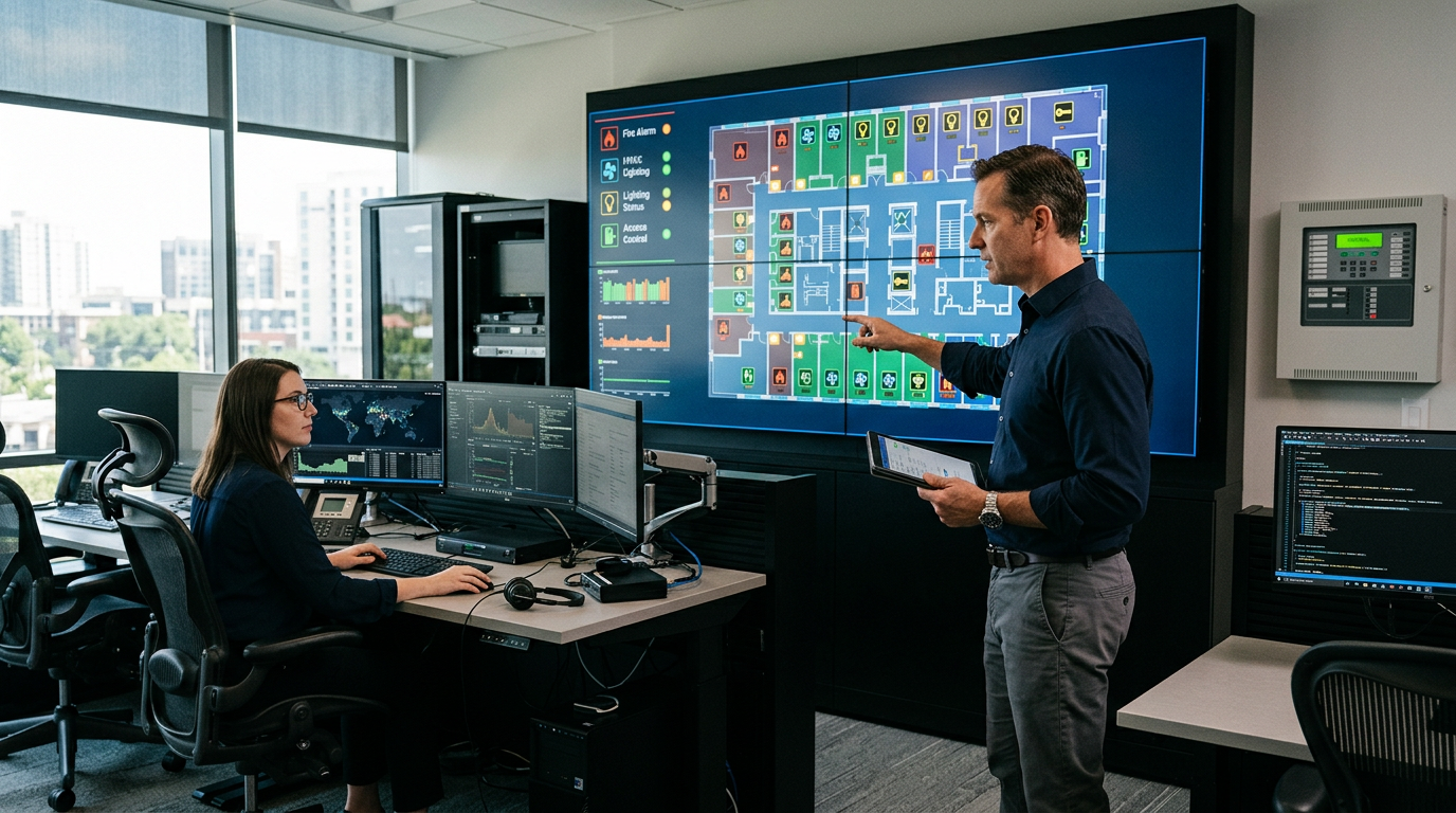
Smart buildings are characterized by connected systems: HVAC, lighting, security, access control, elevators, and increasingly, fire protection. The promise of the smart building is that systems work together, that data flows between them, and that the building is more efficient, more comfortable, and safer as a result. The reality is more complex, especially for fire protection.
Fire safety in smart buildings is the discipline of connecting fire protection systems to building networks without compromising their reliability, their code compliance, or their cybersecurity. The fire alarm system is no longer a standalone panel; it may be connected to a cloud platform, integrated with building automation, monitored from a remote location, and supplemented by IoT sensors. Each of these connections introduces benefits and risks.
The benefits are real. Real-time monitoring can detect impairments faster, data analytics can identify trends, and integration can improve emergency response. But the risks are also real. A cyberattack on a connected fire alarm system could disable detection or notification. A network outage could interrupt remote monitoring. An integration error could cause the system to respond incorrectly. The fire protection system is a life safety system, and it must remain functional even when the network is not.
This article covers the integration models, the benefits and risks, the role of IoT devices, cybersecurity, the code and standards framework, integration testing, data analytics, operations and lifecycle management, and how to design smart building fire protection that is both connected and reliable.
Section 1: What Smart Building Integration Means for Fire Protection
Smart building integration for fire protection takes several forms, each with different benefits and risks.
| Model | Description | Benefits | Risks |
|---|---|---|---|
| Standalone | Fire alarm panel not connected to other systems | Highest reliability; no network dependency | Limited data; manual monitoring |
| Monitored (traditional) | Panel connected to a supervising station via cellular, IP, or radio path | Remote monitoring; dispatch | Communication path dependency |
| Building automation integration | Panel shares data with the BAS | Coordinated response; data visibility | Integration errors; BAS failure |
| Cloud-connected | Panel or gateway connected to a cloud platform | Remote diagnostics; analytics; mobile alerts | Cybersecurity; network dependency |
| Full integration | Multiple systems share data and control | Optimized response; continuous monitoring | Complexity; cascading failures |
A. The Core Tension
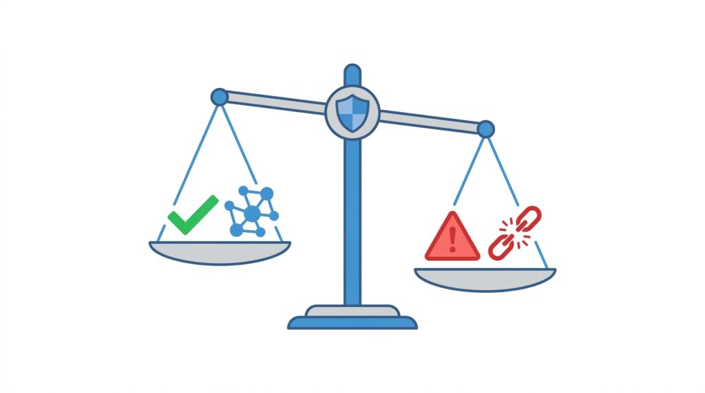
The core tension in smart building fire protection is between connectivity and reliability. Every connection is a potential failure point. The more connected the system, the more benefits it provides, and the more failure modes it has.
B. The Life Safety Constraint
Fire protection systems are life safety systems. They must function when the network is down, when the power is out, and when the building is under stress. A connected system that depends on the network to function is not a reliable life safety system.
C. Supervising Station Monitoring vs. Cloud Connectivity
Two things are often confused. Supervising station monitoring (NFPA 72, Chapter 26) is the code-required transmission of alarm, supervisory, and trouble signals to a listed or approved supervising station, using approved communication paths. Cloud connectivity is typically an added service for diagnostics, analytics, and mobile notifications. Unless the AHJ has approved it as part of the required signaling path, a cloud platform is a supplement, not a substitute, for supervising station monitoring.
D. Communication Paths
The communication path is where many smart-building projects succeed or fail. Traditional copper telephone lines are being retired by carriers, and older cellular technologies have been sunset, which has left many legacy communicators unable to transmit. When designing or upgrading:
- Use communicators and paths permitted by NFPA 72 and the AHJ (IP, cellular, radio, or approved combinations).
- Provide redundancy: a second, independent path where required or where reliability demands it.
- Confirm supervision of the path, so a failed connection produces a trouble signal.
- Plan for carrier technology changes; a communicator that works today may not work after the next network retirement.
Key point: The fire protection system must remain functional independently of the network. Connectivity is an enhancement, not a dependency.
Key Article: Article 146, Integrated Testing of Fire and Life Safety Systems
Pro Tip: For every connected fire protection system, ask: “What happens if the network fails?” If the answer is “the system stops working,” the design needs to change.
Section 2: The Benefits of Smart Integration
Smart building integration offers real benefits when it is designed and implemented correctly.
A. Faster Detection of Impairments
Connected systems can report impairments (closed valves, trouble signals, battery faults) to a monitoring platform in real time, so they can be addressed faster than with periodic inspection alone.
B. Data Analytics
Data from fire protection systems can reveal trends such as repeated trouble signals on a specific device, gradual changes in water pressure, and patterns of alarm activations. Analytics can identify issues before they become failures.
C. Remote Diagnostics
Technicians can diagnose issues remotely, reducing response time and improving first-time fix rates.
D. Improved Emergency Response
Integration with building systems can improve emergency response: elevators recall automatically, doors release for egress, HVAC responds to prevent smoke spread, and mass notification activates.
E. Compliance and Documentation
Connected systems can generate ITM records automatically, reducing administrative burden and improving record completeness.
Key point: Smart integration offers faster impairment detection, data analytics, remote diagnostics, improved response, and automated documentation.
Pro Tip: Start with the benefits that address your biggest challenges. If impairment detection is a problem, focus on that; if documentation is a problem, focus on that.
Section 3: The Risks of Smart Integration
Every connection introduces risk. The risks must be identified and managed.
A. Cybersecurity Risks
| Risk | Consequence |
|---|---|
| Unauthorized access | Attacker disables detection or notification, or triggers false alarms |
| Malware or ransomware | System compromised; false alarms or silence; loss of records |
| Data breach | Building data exposed; privacy violation |
| Denial of service | System or monitoring unavailable when needed |
| Compromised vendor access | Attacker reaches the system through a contractor or cloud provider |
B. Network Dependency
If the fire alarm system depends on the network to function, a network outage is a fire protection outage.
C. Integration Errors
Integration between systems can introduce incorrect data mapping, conflicting control sequences, timing issues, and cascading failures.
D. Vendor Lock-In and Obsolescence
Proprietary systems can lock the owner into a single vendor for maintenance, upgrades, and support. Connected systems may also become obsolete faster than standalone systems, since software, hardware, and vendor support are ongoing requirements.
E. False Alarms and Alert Fatigue
More data means more alerts. If operators receive too many low-value notifications, they begin to ignore them, and a real impairment can be missed.
F. Regulatory Uncertainty
Some AHJs have specific requirements for connected systems; others do not. The regulatory landscape is evolving.
Key point: Smart integration introduces cybersecurity, network dependency, integration error, vendor lock-in, obsolescence, alert fatigue, and regulatory risks. Each must be identified and managed.
Pro Tip: Include cybersecurity in the fire protection design review. The fire alarm system is a life safety system and must be protected accordingly.
Section 4: IoT Devices and the Listed Fire Protection System
The “internet of things” brings low-cost wireless sensors, smart valves, and connected devices into buildings. They can add useful data, but they are not the same as listed fire protection equipment.
A. Listed vs. Non-Listed Devices
Detection, notification, and supervisory devices that satisfy a code requirement must be listed for fire alarm service and installed in accordance with NFPA 72 and the manufacturer’s listing. A general-purpose IoT smoke, heat, temperature, or water sensor is typically not listed for this purpose.
| Use | Acceptable approach |
|---|---|
| Code-required detection or notification | Listed devices connected to the listed fire alarm control unit |
| Valve and water flow supervision | Listed supervisory switches and waterflow devices; IoT sensors may add data but do not replace them |
| Early warning, trending, or operational awareness | IoT sensors as a supplement, clearly separated from the life safety system |
| Wireless devices within the fire alarm system | Listed wireless devices, with the signal strength and battery supervision NFPA 72 requires |
B. Rules for Integrating IoT Data
- IoT data should not be the only means of detecting a fire or an impairment where the code requires listed devices.
- A failure of an IoT sensor or platform must never cause the fire alarm system to fail, alarm falsely, or silence.
- Data from non-listed devices should enter the fire alarm system, if at all, only through approved interfaces and with AHJ acceptance.
- Document clearly which devices are life safety and which are supplemental, so that inspectors, operators, and future designers do not confuse them.
C. Emerging Technologies
Video-based flame and smoke detection, AI-assisted analytics, and digital twins are expanding quickly. Where they are used for code-required detection, they must be listed and accepted by the AHJ. Where they are used for situational awareness, they should be designed as supplements. See the planned Article 158 on digital twins for fire safety management.
Key point: IoT sensors can enrich the picture, but listed devices remain the basis of the life safety system.
Pro Tip: Label every device and data point as “life safety” or “supplemental” in the design documents and the monitoring platform.
Section 5: Integration with Other Building Systems
Integration with BAS, access control, elevators, and mass notification is where most smart-building benefits, and many failures, occur.
A. Control Direction
The fire alarm system should control the other systems, not the reverse. In general:
- Signals flow from the fire alarm system to the BAS for monitoring and for coordinated responses.
- Commands from the BAS to the fire alarm system (such as remote silence or reset) should be avoided unless the listing and the AHJ allow them.
- Data-only gateways (for example, read-only BACnet or Modbus interfaces) are preferred for monitoring.
- Smoke control systems must use equipment and sequences listed and tested for that purpose; they should not be handled as ordinary BAS points.
B. Access Control and Egress
Electrically locked egress doors must release on fire alarm activation and on loss of power, in accordance with NFPA 101 (§7.2.1.5 and §7.2.1.6) and the IBC. Security “lockdown” functions must be coordinated so they never prevent egress required by the code. This interface must be tested, not assumed.
C. Elevators
Elevator recall and shunt trip interfaces are governed by ASME A17.1 and NFPA 72, and must be tested with the elevator contractor present.
D. Mass Notification
Mass notification systems (UL 2572; NFPA 72, Chapter 24) may share infrastructure with fire alarm systems. Priority rules must make sure a fire alarm message is never overridden by a lower-priority message.
E. Network Power and Pathways
If network equipment (switches, media converters, gateways) carries fire alarm signals, it becomes part of the fire alarm pathway. It must meet the NFPA 72 requirements for secondary power, supervision, pathway survivability, and installation (NFPA 70, Article 760 for fire alarm circuits). Standard office-grade network gear on a general building UPS typically does not meet these requirements.
Key point: Treat every interface as a life safety interface: define the direction of control, the failure behavior, and the test.
Pro Tip: Document each interface in a sequence-of-operations matrix that shows what happens when either side fails.
Section 6: Cybersecurity for Fire Protection Systems
Cybersecurity is the most significant new risk introduced by smart building integration.
A. The Standard Framework
| Standard | Scope |
|---|---|
| UL 2900-1 | Software cybersecurity for network-connectable products |
| IEC 62443 | Security for industrial automation and control systems (zones, conduits, security levels) |
| ISO/IEC 27001 | Information security management systems |
| NIST Cybersecurity Framework | Risk-based cybersecurity framework |
B. The Design Principles
| Principle | Application |
|---|---|
| Least privilege | Users have only the access they need |
| Network segmentation | Fire alarm system isolated from the general building network |
| Encryption | Data encrypted in transit and at rest where supported |
| Authentication | Strong, multi-factor authentication for all remote access; no default credentials |
| Monitoring and logging | Continuous monitoring and audit logs of access and configuration changes |
| Patch management | Controlled updates for known vulnerabilities |
| Backup and recovery | Offline backups of panel programming and configuration |
| Incident response | Plan for responding to a cyber incident |
C. Network Segmentation
The fire alarm system should be isolated from the general building network, ideally on a dedicated network or a firewalled segment (not simply a shared VLAN). Where data must leave the fire alarm network, use a controlled gateway that limits what can pass, and consider a one-way (read-only) path for monitoring. This limits the attack surface and prevents lateral movement from a compromised system.
D. Remote Access
Remote access is the most common route for attackers and also one of the most valuable features for technicians. Control it:
- Distinguish remote viewing and diagnostics from remote control and programming. Remote programming, silencing, and resetting should be allowed only where the listing, the AHJ, and the owner’s policy permit.
- Use secure, encrypted access with multi-factor authentication, per-user accounts, and time-limited vendor access.
- Log every session and review the logs.
E. Third-Party and Supply Chain Risk
Vendors, cloud providers, and central stations are part of the attack surface. Contracts should address security requirements, breach notification, data ownership, software updates, and what happens if the vendor ends support or goes out of business.
F. Cyber Incident Response
The response plan should define who is notified, how the system is verified after an incident, and how fire safety is maintained in the interim (for example, impairment procedures and a fire watch if protection is compromised).
G. The AHJ’s Role
Some AHJs require that the connection be approved, that the fire alarm equipment be listed, or that specific cybersecurity measures be taken. Others have no specific requirements. The AHJ’s interpretation determines the compliance path.
Key point: Cybersecurity is a life safety issue for connected fire protection systems. The design must include segmentation, authentication, monitoring, backups, and incident response.
Pro Tip: Include the IT security team in the fire protection design review. The fire alarm system must be protected to the same standard as other critical systems.
Section 7: The Code and Standards Framework
Smart building integration for fire protection is governed by a combination of fire codes, electrical codes, and cybersecurity standards.
A. NFPA 72
NFPA 72 establishes requirements for fire alarm systems, including supervising station and remote monitoring (Chapter 26), communication paths, pathway survivability, secondary power, documentation, and reacceptance testing after software or hardware changes. Recent editions have expanded provisions on communication methods and connectivity. Confirm exactly what your adopted edition says before relying on any cloud or remote function.
B. UL 864 and Listing
UL 864 is the standard for fire alarm control units and accessories. Equipment that performs fire alarm functions, and the communicators and gateways that carry its signals, must be listed for that purpose. Listing of the fire alarm control unit does not by itself prove the cybersecurity of a connected platform.
C. UL 2900-1 and IEC 62443
UL 2900-1 evaluates the cybersecurity of network-connectable products. IEC 62443 addresses security for systems and networks. Specify them, or an equivalent, for connected products and ask vendors for evidence of conformity.
D. NFPA 70
The National Electrical Code governs wiring, including fire alarm circuits (Article 760) and communications cabling. Fire alarm and general network cabling must be installed and separated as the code requires.
E. The IFC and IBC
The IFC and IBC establish the general requirements for fire protection systems, including monitoring of required fire alarm systems (IFC §907.6.6) and impairment procedures. They may include provisions for remote monitoring and connected systems.
F. The AHJ’s Requirements
The AHJ determines the specific requirements for connected systems in its jurisdiction. Some AHJs require approval of the connection; others require specific cybersecurity measures.
Key point: NFPA 72, listing requirements, UL 2900-1, IEC 62443, and the AHJ’s requirements together determine the compliance path.
Pro Tip: For any connected fire protection system, verify the listing and the AHJ’s requirements before design. The compliance path is not always clear.
Section 8: Integration Testing and Commissioning
Integrated systems must be tested as a system, not as individual components. The integration is where failures occur.
A. The Test Scope
| Test | Purpose |
|---|---|
| Component testing | Verify each component functions |
| Interface testing | Verify data flows correctly between systems |
| Sequence testing | Verify the correct sequence of operations |
| Failure testing | Verify the system responds correctly to failures |
| Cybersecurity testing | Verify the system resists attack |
B. NFPA 3 and NFPA 4
NFPA 3 addresses commissioning of fire protection and life safety systems, and NFPA 4 addresses integrated testing of those systems. Together they call for a commissioning and integrated test plan, test procedures, acceptance criteria, qualified personnel to lead the integrated tests, and documentation. Cybersecurity verification is generally outside the scope of NFPA 4, so it should be specified separately (for example, against UL 2900-1 or IEC 62443) and coordinated with the integrated test plan.
C. The Failure Scenarios
Integration testing should include failure scenarios:
- What happens if the network fails?
- What happens if the BAS fails?
- What happens if the cloud platform or supervising station path is unavailable?
- What happens if primary power is lost and the system runs on standby power?
- What happens if a cyberattack or credential compromise occurs?
The system should respond correctly to each failure, and the supervising station and the building operators should receive the correct trouble signals.
D. Retesting After Changes
Software and firmware updates, new integrations, and network changes can alter system behavior. NFPA 72 requires reacceptance testing after modifications, and the extent depends on the change. Build a change-control process so that no update to a connected component is applied without evaluating what must be retested.
Key point: Integration testing verifies that the system works as a system. The test must include failure scenarios, not just normal operation, and must be repeated when the system changes.
Key Article: Article 146, Integrated Testing of Fire and Life Safety Systems
Pro Tip: Include failure scenarios in the integration test plan. The system’s response to failure is as important as its normal operation.
Section 9: Data Analytics and Predictive Maintenance
Connected fire protection systems generate data that can support predictive maintenance.
A. The Data Sources
| Source | Data |
|---|---|
| Fire alarm panel | Trouble signals, alarm history, device status |
| Sprinkler system | Pressure, flow, valve position |
| Fire pump | Run status, pressure, flow |
| Inspection records | ITM results, deficiencies |
| Environmental sensors | Temperature, humidity |
B. The Analytics
| Analysis | Purpose |
|---|---|
| Trend analysis | Identify gradual changes |
| Pattern recognition | Identify recurring issues |
| Anomaly detection | Identify unusual events |
| Predictive maintenance | Predict failures before they occur |
Used well, analytics can reduce unplanned failures, extend equipment life, improve compliance, and lower maintenance costs.
C. The Limitations
Data analytics is not a substitute for inspection. The data is only as good as the sensors that generate it, and the analytics must be validated against actual conditions. NFPA 25 and the IFC still require physical inspection, testing, and maintenance, and the required ITM frequencies and records are not reduced because a system is connected, unless the AHJ explicitly accepts an alternative.
D. Data Governance and Privacy
Fire protection data may include building layouts, occupant patterns, and system weaknesses. Define who owns the data, where it is stored, who can access it, how long it is retained, and how it is deleted. Confirm that any cloud provider’s terms are consistent with the owner’s policies and applicable privacy and records-retention requirements.
Key point: Data analytics can improve maintenance and compliance, but it does not replace inspection. The data supports the inspection; it does not replace it.
Pro Tip: Start with a small pilot. Use the data from a few systems to validate the analytics before expanding.
Section 10: Operations, Impairments, and Lifecycle Management
A well-designed connected system still fails if no one is responsible for it. Operations is where long-term reliability is won or lost.
A. Roles and Responsibilities
Define who receives alerts, who responds, and who has authority to act. Fire protection, facility management, IT, the fire alarm contractor, and the central station each have a role; gaps between them are where signals get lost. Document an escalation path for after-hours alerts.
B. Alert Management
Tune alert thresholds so that operators receive meaningful, prioritized notifications. Separate life safety alarms and impairments from routine analytics notices. Review alert history periodically to remove noise.
C. Impairment Procedures
A connected platform may report an impairment faster, but the response is still governed by the impairment program in NFPA 25 (Chapter 15), NFPA 72, and IFC §901.7: notify the AHJ and insurer as required, implement a fire watch or other interim measures where needed, and restore the system promptly. A cyber incident that compromises the system should be treated as an impairment.
D. Software, Firmware, and Hardware Lifecycle
- Keep an inventory of connected devices, software versions, and support end dates.
- Apply updates through a controlled process with testing and rollback plans.
- Plan and budget for replacement before vendor support ends.
- Retain current backups of panel programming, network configuration, and as-built documentation.
E. Training
Train operators, security staff, and facility personnel on what the system does, what the alerts mean, and what to do when the network or platform is unavailable.
Key point: Reliability depends on clear responsibility, controlled change, and a plan for the whole life of the system.
Pro Tip: Write a one-page “what to do when the network or the platform is down” procedure and post it where operators can find it.
Section 11: Implementation Roadmap
Implementing smart building integration for fire protection requires a phased approach.
| Phase | Activities |
|---|---|
| 1. Assess | Identify current systems, integration opportunities, and risks |
| 2. Define | Define the integration scope, benefits, and requirements |
| 3. Design | Design the integration architecture, cybersecurity, and testing |
| 4. Select | Select vendors and products that meet the requirements |
| 5. Test | Test the integration, including failure scenarios |
| 6. Deploy | Deploy with monitoring and support |
| 7. Operate | Operate, monitor performance, and improve |
A. The Pilot Approach
For organizations new to smart integration, a pilot is recommended. Start with a single building or a single system, learn from the experience, and then expand.
B. Procurement and Contract Considerations
- Require open, documented protocols and interfaces to reduce vendor lock-in.
- Require evidence of listings and cybersecurity conformity (UL 864, UL 2900-1, IEC 62443 or equivalent).
- Define service levels, support life, and security update commitments.
- Define data ownership, access, and an exit plan if the vendor or platform is replaced.
- Specify who is responsible for integrated testing and for retesting after changes.
C. Stakeholder Engagement
Smart integration requires engagement from the fire protection engineer, the IT security team, facility management, the fire alarm contractor, the BAS contractor, the AHJ, and the insurer.
Key point: Smart integration is a multi-disciplinary project. The fire protection engineer must be involved from the beginning.
Pro Tip: Include the AHJ and the IT security team in the design phase. Their input determines the compliance and security path.
Section 12: Common Challenges and Mistakes
| Challenge or mistake | Why it happens | How to avoid it |
|---|---|---|
| Assuming the network is always available | System designed to depend on the network | Design for standalone operation |
| Cybersecurity not addressed | Not in scope or not assigned | Include in design review; engage IT security |
| Treating IoT sensors as listed devices | Low cost, convenient data | Keep listed devices as the life safety basis |
| Network gear not meeting fire alarm requirements | Office-grade equipment reused | Meet NFPA 72 pathway and power requirements |
| Integration errors | Interfaces not tested | Integrated testing with failure scenarios |
| Vendor lock-in and obsolescence | Proprietary systems; no lifecycle plan | Require open standards; plan upgrades |
| AHJ unfamiliar with connected systems | New technology | Hold a pre-submittal meeting |
| Data analytics not validated | Assumed accurate | Validate against inspection |
| Updates applied without retesting | No change control | Define a change and retest process |
| Alert overload | Too many low-value notifications | Prioritize and tune alerts |
| Insurer requirements not met | Not aware | Obtain requirements in writing |
Key point: Most smart building integration failures are not technical failures. They are failures to integrate the fire protection, IT security, and operations perspectives.
Pro Tip: For any smart integration project, hold a kickoff meeting that includes fire protection, IT security, facility management, and the AHJ.
Section 13: Design Checklist
| Item | Status | Notes |
|---|---|---|
| Integration scope defined | ☐ | Which systems; which connections |
| Benefits and risks documented | ☐ | For each integration |
| Life safety vs. supplemental devices identified | ☐ | Listed devices vs. IoT |
| Communication paths designed | ☐ | Redundancy; supervision; carrier changes |
| Network architecture designed | ☐ | Segmentation; power; pathway survivability |
| Control direction and interfaces defined | ☐ | BAS, access control, elevators, MNS |
| Cybersecurity measures specified | ☐ | UL 2900-1, IEC 62443; remote access controls |
| Standalone operation verified | ☐ | System functions without the network |
| Failure scenarios tested | ☐ | Network, BAS, cloud, power, cyber |
| Integrated testing specified | ☐ | Per NFPA 3 and NFPA 4 |
| AHJ requirements confirmed | ☐ | Connected systems |
| Insurer requirements obtained | ☐ | In writing |
| IT security team engaged | ☐ | Design review |
| Operations and impairment procedures | ☐ | Roles, alerts, network-down procedure |
| Change control and lifecycle plan | ☐ | Updates, retesting, backups, end of support |
| Procurement terms defined | ☐ | Open standards, data ownership, exit plan |
| Data analytics plan | ☐ | If applicable; validated against inspection |
| Implementation roadmap | ☐ | Phased approach with pilot |
Section 14: Conclusion
Smart building integration offers real benefits for fire protection: faster impairment detection, data analytics, remote diagnostics, improved response, and automated documentation. It also introduces real risks: cybersecurity, network dependency, integration errors, vendor lock-in, obsolescence, and regulatory uncertainty.
The critical elements are:
- Benefits and risk assessment: what the integration will achieve and what it introduces
- Listed life safety devices: IoT data supplements, but does not replace, listed equipment
- Reliable communication paths: redundant, supervised, and ready for carrier changes
- Cybersecurity: segmentation, controlled remote access, authentication, monitoring, and backups
- Standalone operation: the system functions without the network
- Integration testing: including failure scenarios and retesting after changes
- AHJ and IT security coordination: the regulatory and security paths
- Operations and lifecycle: clear responsibilities, impairment procedures, and controlled updates
- Phased implementation: pilot, learn, expand
The most common failure is treating smart integration as a technology project rather than a life safety project. The fire protection system must remain functional independently of the network, and the integration must be designed, tested, and operated with life safety as the primary objective.
Key Takeaways:
- Smart building integration offers real benefits for fire protection.
- Every connection introduces risk: cybersecurity, network dependency, integration errors.
- The fire protection system must remain functional independently of the network.
- Supervising station monitoring is the code-required path; cloud connectivity is generally a supplement.
- Listed devices remain the basis of the life safety system; IoT sensors are supplemental.
- Cybersecurity is a life safety issue for connected fire protection systems.
- Integration testing must include failure scenarios and be repeated after changes.
- Data analytics can support predictive maintenance but does not replace inspection.
- The AHJ and IT security team must be engaged early.
- The most common failure is treating smart integration as a technology project rather than a life safety project.
Take Action Today:
- Define the integration scope and objectives.
- Identify which devices and data are life safety and which are supplemental.
- Review communication paths for redundancy and carrier changes.
- Design the network architecture with segmentation, power, and pathway requirements.
- Specify cybersecurity measures and remote access controls.
- Verify the system functions independently of the network.
- Define failure scenarios and include integrated testing in the project scope.
- Confirm AHJ requirements and obtain insurer requirements in writing.
- Engage the IT security team in the design review.
- Establish operations, impairment, and change-control procedures.
- Plan a phased implementation with a pilot.
Continue Reading from Our Series:
- Related guide: Article 156, Flood, Wind, and Seismic Resilience and Fire Safety
- Related guide: Article 146, Integrated Testing of Fire and Life Safety Systems
- Read more: Article 158, Digital Twins for Fire Safety Management (planned)
About This Guide: This article is part of a series on commercial building fire safety, written for facility managers, architects, and code officials. It references model codes and standards for educational purposes. Always consult your local AHJ, your insurer, and your IT security team for project-specific requirements.