IMPORTANT DISCLAIMER: This guide references NFPA 4, Standard for Integrated Fire Protection and Life Safety System Testing; NFPA 3, Standard for Commissioning of Fire Protection and Life Safety Systems; NFPA 1, Fire Code; NFPA 101, Life Safety Code; NFPA 70, National Electrical Code; NFPA 72, National Fire Alarm and Signaling Code; NFPA 13 (sprinkler systems); NFPA 14 (standpipe and hose systems); NFPA 17A (wet chemical extinguishing systems); NFPA 20 (stationary pumps for fire protection); NFPA 25 (inspection, testing, and maintenance of water-based systems); NFPA 80 (fire doors and other opening protectives); NFPA 90A (air-conditioning and ventilating systems); NFPA 92 (smoke control systems); NFPA 110 (emergency and standby power systems); NFPA 2001 (clean agent fire extinguishing systems); the International Building Code (IBC), including §909 (smoke control); the International Fire Code (IFC), including §901.5 (acceptance testing), §901.6 (inspection, testing, and maintenance), and Chapter 9; ASME A17.1/CSA B44 (Safety Code for Elevators and Escalators); and the building owner’s project requirements (OPR) and basis of design (BOD). Integrated testing requirements vary by jurisdiction, system complexity, and building type. Section numbers and requirements cited here follow the model codes and standards and may differ in your adopted edition. Local amendments and the edition adopted by your Authority Having Jurisdiction (AHJ) always control. This guide is a starting point only. Always verify the requirements applicable to your project with your AHJ.
Individual fire protection systems are tested to their own standards. The sprinkler system is tested to NFPA 13, the fire alarm to NFPA 72, the smoke control system to NFPA 92, and the fire pump to NFPA 20. Each test verifies that a system performs as designed. What these tests do not verify is whether the systems work together: whether a sprinkler flow causes the alarm to sound, whether smoke detection causes the correct dampers to open, whether the elevator recalls to the right floor, whether stair pressurization starts in the correct sequence.
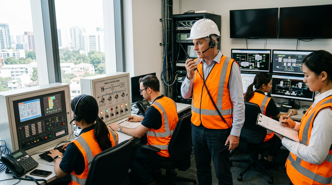
Integrated testing verifies the interaction between fire protection and life safety systems. It catches interface failures, the failures that occur at the boundaries between systems, where no single contractor is responsible and where individual acceptance tests do not reach. NFPA 4 establishes the requirements for integrated testing, and NFPA 3 establishes the commissioning process within which it occurs.
The stakes are high. A valve left closed, a signal that was never programmed, a damper that did not open, a door that did not release: each is an installed system that does not function as part of the whole.
This article covers what integrated testing is, how it differs from acceptance testing, the NFPA 4 framework, the sequence of operations and input/output matrix, test scenarios, acceptance criteria, test methods and safety, execution, documentation, periodic retesting, special cases, and common failures.
◆ Section 1: Why Integrated Testing Matters
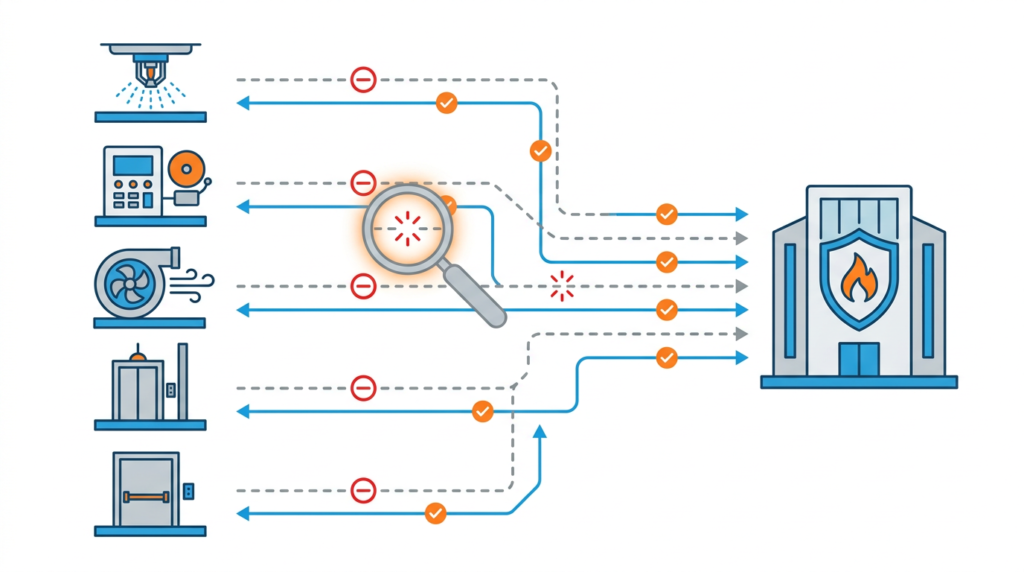
Fire protection systems are designed and installed by different parties, at different times, under different contracts. The sprinkler, fire alarm, smoke control, electrical, and mechanical contractors each test their own work. No one tests whether the systems work together unless integrated testing is part of the project.
The failures integrated testing catches are typically interfaces, not components:
| Failure | Interface |
|---|---|
| Sprinkler flow does not activate alarm | Flow switch → fire alarm panel |
| Alarm does not recall elevator | Fire alarm panel → elevator controller |
| Elevator power not removed when required | Heat/smoke detection → shunt trip → elevator controller |
| Smoke detection does not open dampers | Fire alarm panel → smoke control panel → damper actuators |
| Fire door does not release | Fire alarm panel → door hold-open device |
| Stair or egress doors do not unlock | Fire alarm panel → access control / electromagnetic locks |
| Stair pressurization does not activate | Fire alarm panel → fan controller → damper |
| HVAC does not shut down | Fire alarm panel → air handler / building automation system |
| Generator does not carry fire pump | Generator → transfer switch → fire pump controller |
| Mass notification does not reach all zones | Fire alarm panel → mass notification panel → speakers |
| Kitchen hood discharge does not shut off fuel/power | Suppression system → fuel/electric shutoff → fire alarm panel |
| Smoke control runs in wrong order | Smoke control panel → fans, dampers, doors |
Each of these can be a system that was installed correctly, tested individually, and still does not work as part of the whole.
Code basis. NFPA 4 is the reference standard. Recent editions of the IFC require interconnected fire protection and life safety systems to be tested in an integrated manner per NFPA 4, both at acceptance and on an ongoing basis (see IFC §901.5.2 and §901.6.2; verify the section numbers in your adopted edition). Where the code is silent, the owner, insurer, or AHJ may still require it.
Key point: Integrated testing verifies the interfaces between systems. Interfaces are where failures occur, and they are what individual acceptance testing does not cover.
Key Article: Article 145, Commissioning Fire Protection Systems
Pro Tip: The most valuable integrated test exercises the most important interfaces at once. A sprinkler flow test that also verifies alarm, notification, elevator recall, smoke control, and fire department notification tests the building, not the components.
◆ Section 2: Integrated Testing vs. Acceptance Testing
| Aspect | Acceptance Testing | Integrated Testing |
|---|---|---|
| Purpose | Verifies an individual system meets its standard | Verifies multiple systems work together |
| Scope | Single system | Multiple systems and their interfaces |
| Standard | NFPA 13, 14, 20, 72, 92, etc. | NFPA 4 |
| Who performs | Installing contractor; AHJ may witness | Integrated test team led by the integrated testing agent; AHJ may witness |
| Documentation | Acceptance report per system standard | Integrated test report per NFPA 4 |
| Timing | At completion of each system | After all systems are installed and individually accepted |
| Failure caught | Component or system failure | Interface failure |
Acceptance testing is necessary but not sufficient. A building can have every system pass acceptance testing and still fail integrated testing.
Integrated testing builds on acceptance testing. If a system has not passed its own acceptance test, integrated testing of its interfaces cannot proceed meaningfully, because it would be testing an unverified component.
Key point: Acceptance testing verifies the components; integrated testing verifies the whole. Neither replaces the other.
Pro Tip: Schedule integrated testing after all acceptance testing is complete. Testing interfaces before the components are verified wastes time and produces inconclusive results.
◆ Section 3: The NFPA 4 Framework
NFPA 4 defines the integrated testing process, including the plan, the people, the procedures, the acceptance criteria, the documentation, and the ongoing retesting.
A. The Integrated Testing Agent and Team
| Role | Responsibility |
|---|---|
| Owner | Ultimately responsible for ensuring integrated testing is planned, performed, and maintained; designates the integrated testing agent |
| Integrated testing agent (ITA) | Qualified individual or firm that develops the plan, directs the testing, and prepares the report |
| System representatives | One per system (fire alarm, sprinkler, smoke control, elevator, electrical, HVAC/BAS, access control, etc.); operate and verify their system |
| Witnesses | AHJ, owner, insurer, commissioning authority |
| Recorder | Documents the procedure and results |
| Safety officer | Ensures the test is conducted safely |
NFPA 4 expects the ITA to be qualified for the role. Qualifications should be confirmed in the contract documents and acceptable to the AHJ.
B. The Integrated Test Plan (ITP)
The ITP is the governing document. It specifies:
| Element | Content |
|---|---|
| Scope | Which systems and interfaces are included |
| Team | Who is responsible for each element |
| Matrix | The input/output (cause-and-effect) matrix being verified |
| Scenarios | Which integrated test scenarios are performed |
| Procedures | Step-by-step procedures for each scenario |
| Acceptance criteria | What constitutes a pass |
| Schedule | When each test is performed |
| Safety and impact controls | Notifications, system impairments, protection of occupants and property |
| Documentation | What records are produced |
| Contingencies | What happens if a test fails |
C. Test Procedures
Each scenario should have a written procedure that includes the purpose, preconditions, step-by-step actions, expected response at each step, acceptance criteria, documentation requirements, and return-to-normal steps.
Key point: The ITP is the roadmap for the test. A plan written after the test is not a plan; it is a description of what happened.
Key Article: Article 141, Fire Safety Management Systems and ISO 31000 Alignment
Pro Tip: Write the ITP during design, not after construction. Defining what will be tested early ensures the systems are designed to be testable.
◆ Section 4: The Sequence of Operations and Input/Output Matrix
The sequence of operations defines how the systems should respond in a fire. It is the basis for integrated testing.
A. What the Sequence Defines
| Element | Example |
|---|---|
| Initiating device | Sprinkler flow switch, smoke detector, pull station, suppression release |
| Alarm panel response | Activates alarm; sends signals to notification, monitoring, elevator, smoke control |
| Notification | Alarm in affected zones; voice message |
| Elevator response | Recall to designated or alternate floor; shunt trip where required |
| Smoke control response | Fans start; dampers open/close; doors release |
| HVAC response | Air handlers shut down or switch to smoke control mode |
| Door and lock response | Hold-open release; magnetic and access control locks release |
| Fire department notification | Signal to monitoring company |
| Time delays | Any intentional delay between initiation and response |
| Priority | Which response takes precedence when multiple events occur |
B. The Input/Output Matrix
The sequence is usually presented as a matrix (also called a cause-and-effect matrix): inputs (initiating devices and zones) down the side, outputs (every system response) across the top, with each intersection showing whether the output is required. The matrix is the checklist for integrated testing: every required intersection should be verified, and every unexpected output should be flagged. NFPA 3 and NFPA 4 both rely on it.
C. Why It Matters
The sequence is the specification for the test. If the sequence is wrong, the systems will respond wrong, and the test will confirm that they respond as specified. Review the sequence with the AHJ and owner before installation.
D. Who Prepares It
The fire protection engineer (complex buildings), the fire alarm contractor (simpler buildings), or the design team as part of the basis of design.
Key point: A test without a sequence of operations is a test without a standard.
Key Article: Article 117, Smoke Control System Design and Testing (NFPA 92)
Pro Tip: Changes to the sequence after construction are expensive and can delay occupancy. Resolve them in design.
◆ Section 5: Integrated Test Scenarios
Scenarios exercise multiple systems together. They should test the most important interfaces in the building.
A. Common Scenarios
| Scenario | Systems Exercised | Key Interfaces |
|---|---|---|
| Sprinkler flow | Sprinkler, fire alarm, notification, elevator, smoke control, monitoring | Flow switch → alarm panel → all outputs |
| Manual pull station | Fire alarm, notification, elevator, smoke control, door release | Pull station → alarm panel → all outputs |
| Smoke detection | Fire alarm, notification, smoke control, HVAC, door release, elevator | Detector → alarm panel → all outputs |
| Duct detector | Fire alarm, HVAC/BAS | Detector → alarm panel → air handler shutdown |
| Fire pump start | Fire pump, fire alarm, generator, transfer switch | Controller → pump → alarm panel → standby power |
| Loss of normal power | Generator, transfer switches, fire alarm, emergency lighting, pump, smoke control, elevators | Generator → transfer switches → loads |
| Smoke control activation | Smoke control, fire alarm, dampers, fans, doors | Alarm panel → smoke control panel → devices |
| Stair pressurization | Fire alarm, fans, dampers, doors | Alarm panel → fan controller → damper → door force |
| Mass notification | MNS, fire alarm, notification appliances | Alarm panel → MNS panel → speakers |
| Elevator recall | Fire alarm, elevator controller | Alarm panel → elevator controller (primary and alternate floor) |
| Door/lock release | Fire alarm, hold-opens, access control, magnetic locks | Alarm panel → release devices |
| Special hazard release | Clean agent/kitchen suppression, fire alarm, HVAC, fuel/power shutoff | Release → alarm panel → shutdowns |
| Supervisory and trouble | Valves, fire pump, fire alarm, monitoring | Device → panel → monitoring |
B. Choosing Scenarios
Select based on the systems present, the complexity of the interfaces, the life safety criticality of each system, and the requirements of the AHJ, insurer, and owner. Not every scenario applies to every building, but those that matter for life safety must be tested.
C. Failure-Mode Scenarios
Do not test only the “everything works” case. Include:
- Loss of primary power to the fire alarm panel and to smoke control, confirming battery and generator operation.
- Supervisory signals, such as closed valves and low air, reaching the panel and monitoring.
- Trouble conditions, such as open circuits and ground faults, confirming that signals display, transmit, and do not disable other functions.
- Loss of communication between panels (for networked systems) and between the panel and monitoring.
- Multiple simultaneous events and priority handling.
D. Sequence of Testing
- Pre-functional testing of each system
- Functional (acceptance) testing of each system
- Pre-test of each interface
- Integrated testing of complete scenarios
- Retesting after corrections
Key point: Choose scenarios that test the most important interfaces, and include failure modes, not just the normal alarm.
Pro Tip: Draft scenarios in pre-design, refine them in design, and execute them in construction.
◆ Section 6: Acceptance Criteria
Acceptance criteria define what constitutes a pass for each scenario. They should be specific, measurable, documented, and agreed by the owner, AHJ, and insurer before the test.
The examples below are illustrative only. Actual values come from the codes, standards, manufacturer requirements, and the approved design for your project.
| Scenario | Example Acceptance Criteria |
|---|---|
| Sprinkler flow | Alarm initiated within the time required by NFPA 72 (90 seconds is commonly used); notification in all required zones; elevator recall per sequence; smoke control activates per sequence; signal at monitoring company within the specified time |
| Manual pull station | Alarm and notification activate promptly; outputs per matrix; monitoring signal received |
| Smoke detection | Dampers, doors, HVAC, and elevators respond per matrix; signal received |
| Fire pump start | Pump starts and reaches design pressure; panel receives pump running/trouble signals; standby power carries pump where required |
| Loss of normal power | Generator starts and accepts load within the time required by NFPA 110 for its type and level (10 seconds is typical for life safety loads); transfer switches operate; pump, lighting, and alarm panel remain operational |
| Smoke control | Fans and dampers respond within the times required by IBC §909, NFPA 92, and the design; pressure differentials achieved; door opening force within code limits |
| Stair pressurization | Pressure differential within the design range (commonly 0.10 to 0.35 in. w.g. with doors closed); door opening force within limits (commonly 30 lbf maximum) |
Each criterion should be a measurable value (not “works properly”), testable as pass/fail, recorded in the plan, and agreed by the stakeholders.
Key point: Without agreed criteria, the test is subjective.
Pro Tip: Disagreements after the test are hard to resolve and can delay occupancy. Agree on criteria in writing beforehand.
◆ Section 7: Test Methods, Safety, and Impact Management
A. Actual vs. Simulated Activation
Where practical, test by activating the actual initiating device (for example, flowing water through the inspector’s test connection or applying listed smoke to a detector) so that the whole chain is verified. Where actual activation is impractical or hazardous, use simulation or a test mode, and document what was not verified. Typical cases for simulation:
- Suppression agent discharge (verify the release circuit, not the discharge)
- Fuel or power shutoffs that would disrupt critical operations
- Initiating devices in inaccessible or sensitive areas
Simulation must still prove the signal path and the final output device operation wherever safe.
B. Protecting People and Property
- Notify occupants, the fire department, the monitoring company, and the insurer. Place the system on test with the monitoring company per NFPA 72.
- Control water: provide drainage and protection for flow tests.
- Manage smoke: use listed test smoke products and coordinate with detection and smoke control.
- Manage impacts on elevators, access control, HVAC, process equipment, data centers, and critical operations.
- Maintain protection: if any system is impaired for the test, follow the impairment procedure (NFPA 25 and IFC §901.7) and restore it fully afterward.
- Establish stop criteria and give the safety officer authority to stop the test.
C. Documenting Limits
Record every interface that was simulated rather than actually activated, so that later retesting can close the gap.
Key point: A safe test is a test that can be completed and repeated; an unsafe test will be stopped and distrusted.
Pro Tip: Walk through the full procedure as a tabletop exercise with all system representatives before the live test.
◆ Section 8: Executing the Integrated Test
A. Pre-Test
| Activity | Purpose |
|---|---|
| Verify all acceptance tests are complete | Components are verified |
| Verify the sequence and matrix are approved | The standard is agreed |
| Back up and record panel programming and versions | Baseline for comparison and recovery |
| Pre-test each interface | Catches problems before the full test |
| Notify AHJ, fire department, monitoring company, occupants, insurer | Avoids false dispatch and confusion |
| Brief the team and verify communications | Everyone knows their role |
| Establish test boundaries and safety controls | Test is safe and controlled |
B. During the Test
- Follow the written procedure
- Document every step, the expected response, the actual response, and the time
- Record deviations immediately
- Stop the test if it becomes unsafe
C. After the Test
- Document results and deficiencies
- Assign corrections and schedule retesting
- Return systems to normal and confirm full restoration
- Take the monitoring company off test
- Notify the AHJ, fire department, and occupants that testing is complete
Key point: The integrated test is a documented activity. The log is the evidence.
Pro Tip: Use a test log with columns for step, expected response, actual response, time, pass/fail, and responsible person.
◆ Section 9: Deficiencies, Retesting, and Programming Control
A. Handling Deficiencies
Classify each deficiency (life safety critical, functional, or documentation) and track it to closure in the deficiency log, with an owner, a correction, and a retest date.
B. Scope of Retesting
Retest the failed interface and any other interfaces that share the corrected component or programming. A programming fix to one panel output can change others.
C. Software and Programming Control
- Keep a controlled copy of each panel’s program, matrix, and firmware version.
- Require change records and re-verification for changes made during testing.
- Archive the as-tested program with the final report.
- Treat connections between fire alarm and building automation or networked systems with appropriate cybersecurity and access controls.
Key point: An uncontrolled programming change after the test can undo the verification.
Pro Tip: Freeze programming before the integrated test, and require change control during it.
◆ Section 10: Documentation and Reporting
A. Documents
| Document | Content |
|---|---|
| Integrated test plan | Scope, team, scenarios, procedures, criteria |
| Sequence of operations and matrix | The approved versions |
| Pre-test verification | Confirmation acceptance testing is complete |
| Test log | Step-by-step record |
| Deficiency log | Deficiencies identified and corrected |
| Retest report | Results after corrections |
| Final integrated test report | Summary and results |
| AHJ acceptance | AHJ’s acceptance of the results |
B. The Final Report
Include a summary, scenarios tested, results for each, interfaces simulated rather than actually activated, deficiencies and corrections, retest results, confirmation that criteria were met, and signatures of the ITA, AHJ, and owner.
C. Retention
Retain the documentation for the life of the building. It is the baseline for periodic retesting and what the AHJ, insurer, and fire investigator will request.
Key Article: Article 198, Fire Safety Documentation and Record-Keeping Best Practices (planned)
Pro Tip: File the documentation in the building’s fire safety management system.
◆ Section 11: Periodic Integrated Testing
Systems change, degrade, and are modified over the life of a building. Periodic retesting confirms that they continue to work together. Note that periodic integrated testing is in addition to the routine inspection, testing, and maintenance (ITM) of each system under NFPA 25, NFPA 72, NFPA 80, NFPA 92, and others.
A. When Retesting Is Needed
| Situation | Why |
|---|---|
| System modification or replacement | May affect interfaces |
| Panel software or firmware update | May change outputs |
| Change of use or occupancy | May change the sequence |
| Tenant improvements or renovation | May alter zoning, doors, and HVAC |
| Significant incident or near-miss | May reveal interface failures |
| AHJ or insurer requirement | Required by the authority or policy |
| Periodic interval | Set by the AHJ, ITP, and owner’s program |
B. Frequency
NFPA 4 does not impose one universal interval. The frequency should come from the AHJ’s requirements, the ITP, system complexity, occupancy, and insurer requirements. Many owners of complex buildings set a multi-year cycle in their maintenance program; confirm with your AHJ.
C. Scope After Modification
Retest the affected interfaces, with a scope proportional to the change.
Key point: The initial test establishes the baseline; periodic retesting verifies it is maintained.
Key Article: Article 30, Commercial Building Maintenance: Fire Safety Systems and Best Practices
Pro Tip: Put periodic integrated testing in the capital and maintenance plan. The cost is small compared to an interface failure in a fire.
◆ Section 12: Special Cases
A. Smoke Control Systems
The most complex system to test, depending on fans, dampers, fire alarm, doors, HVAC, building automation, and standby power. Follow NFPA 92 and NFPA 4, and coordinate with the special inspector where one is required.
B. Elevators and Occupant Evacuation Elevators
Verify recall to the designated floor, alternate-floor recall when the designated floor is compromised, doors opening, and removal from normal service for fire department use. Where required, verify shunt trip and heat detector operation. For occupant evacuation elevators, verify operation as designed. See ASME A17.1/CSA B44.
C. Mass Notification Systems
Verify activation on the correct signals, message delivery to all zones, intelligibility, and priority over fire alarm where required.
D. Fire Pump and Standby Power
Verify generator start on loss of normal power, transfer switch operation, pump operation on generator power, panel signals, and emergency lighting.
E. Clean Agent, Kitchen, and Special Hazard Systems
Verify detection activates suppression release circuits, suppression activates alarm and notification, HVAC shuts down or dampers close, fuel or power is shut off, discharge is signaled, and post-discharge ventilation operates.
F. Door Hardware and Access Control
Verify release of magnetic locks, delayed egress locks, and access-controlled doors on alarm, and stairwell reentry unlocking where required.
G. Phased Projects, Tenant Improvements, and Existing Buildings
For phased occupancy, test each phase and the interfaces between completed and incomplete areas, and retest as later phases connect. For tenant improvements, test the interfaces the improvement touches. For existing buildings with no baseline, develop the matrix from the as-built conditions and test the critical life safety interfaces first.
Key point: Smoke control, elevators, mass notification, fire pump, special hazard, door hardware, and phased work each need specific attention in the test plan.
Pro Tip: Include the elevator, smoke control, mass notification, and access control contractors in the test. The people who know the systems must operate them.
◆ Section 13: Common Failures, Challenges, and How to Prevent Them
A. Technical Failures
| Failure | Why It Happens | Prevention |
|---|---|---|
| Signal not received at monitoring | Communication path not verified | Pre-test monitoring check |
| Elevator does not recall | Interface not programmed | Pre-test elevator interface check |
| Damper does not open | Wiring not coordinated | Pre-test damper operation |
| Door does not release | Hold-open or lock not wired to alarm | Pre-test door release |
| Fan does not start | Control wiring not coordinated | Pre-test fan operation |
| Sequence runs in wrong order | Sequence incorrect | Verify sequence before test |
| Time delay incorrect | Programming not verified | Pre-test timer check |
| Notification not reaching all zones | Zoning not coordinated | Pre-test notification and zone check |
| Mass notification not overriding | Priority not programmed | Pre-test MNS check |
| Generator does not carry fire pump | Transfer switch sequencing | Pre-test generator/fire pump |
| HVAC keeps running | BAS not coordinated with fire alarm | Pre-test BAS interface |
B. Process Failures
| Challenge | Solution |
|---|---|
| Integrated testing not in the specification | Include it in the project specification |
| Plan written late | Write the plan in design |
| Sequence or matrix not documented | Document and approve before construction |
| Interfaces not assigned to anyone | Assign responsibility in the plan |
| AHJ not engaged | Engage early |
| Contractors unavailable | Include in the project schedule |
| Acceptance testing incomplete | Verify before the test |
| Acceptance criteria not agreed | Agree in writing before the test |
| Simulated items not recorded | Document in the report |
| Programming changed during testing | Use change control |
| Retesting skipped | Schedule and verify corrections |
| Periodic retesting not planned | Include in the capital plan |
Key point: Most integrated test failures are interface failures, and most interface failures are symptoms of process failures: the testing was not scoped, planned, or executed.
Pro Tip: Pre-test each interface before the full scenario. It is cheaper to find a miswired damper in a pre-test than in front of the AHJ.
◆ Section 14: Design and Planning Checklist
| Item | Status | Notes |
|---|---|---|
| Integrated testing scope defined | ☐ | Systems and interfaces |
| ITA designated and qualified | ☐ | Accepted by owner and AHJ |
| Integrated test team identified | ☐ | System representatives and witnesses |
| Sequence of operations documented | ☐ | Approved by owner and AHJ |
| Input/output matrix prepared | ☐ | Every required output listed |
| Integrated test plan prepared | ☐ | Scenarios, procedures, criteria |
| Failure-mode scenarios included | ☐ | Power loss, supervisory, trouble |
| Acceptance criteria agreed | ☐ | Owner, AHJ, insurer |
| Simulation limits identified | ☐ | And documented |
| Safety and impact controls defined | ☐ | Notifications, impairments, drainage |
| Pre-test verification procedure | ☐ | Acceptance testing complete |
| Programming baseline and change control | ☐ | Frozen before test |
| Test and deficiency log templates | ☐ | Ready |
| Notifications planned | ☐ | AHJ, fire department, monitoring, occupants |
| Retesting procedure | ☐ | After corrections |
| Documentation and retention | ☐ | Report and life-of-building retention |
| Periodic retesting planned | ☐ | In capital plan |
◆ Section 15: Conclusion
Integrated testing verifies that fire protection and life safety systems work together. It is distinct from acceptance testing, which verifies individual systems. It catches the interface failures that individual testing does not, the failures at the boundaries between systems where no single contractor is responsible.
NFPA 4 establishes the requirements, and NFPA 3 establishes the commissioning process within which they operate. The integrated test plan is the governing document, the sequence of operations and matrix are the standard, and the acceptance criteria are the measure.
The most common failure is treating integrated testing as an afterthought. It must be planned in design, executed in construction, controlled through programming changes, and documented and repeated over the life of the building.
Key Takeaways:
- Integrated testing verifies that systems work together, not just individually.
- It is distinct from acceptance testing; both are necessary.
- NFPA 4 sets the requirements; NFPA 3 sets the commissioning process; recent IFC editions require integrated testing of interconnected systems.
- The owner designates a qualified integrated testing agent.
- The sequence of operations and input/output matrix are the standard for the test.
- The test plan defines scenarios, procedures, and acceptance criteria, including failure-mode scenarios.
- Acceptance criteria must be specific, measurable, and agreed before the test.
- Actual activation is preferred; document anything simulated.
- Control programming changes and retest every interface affected by a correction.
- The documentation is the evidence the systems were verified together.
- Periodic retesting is in addition to routine ITM and follows AHJ and ITP requirements.
- Smoke control, elevators, mass notification, fire pump, special hazard, and door hardware need specific treatment.
Take Action Today:
- Confirm integrated testing is in the project specification and that the owner has designated a qualified ITA.
- Document the sequence of operations and matrix, and review them with the AHJ.
- Prepare the integrated test plan with scenarios, procedures, and agreed acceptance criteria.
- Plan pre-tests, notifications, safety controls, and programming change control.
- Execute, document, correct, and retest, then plan periodic retesting in the capital plan.
Continue Reading from Our Series:
-
Related guide: Article 145 — Commissioning Fire Protection Systems
-
Related guide: Article 117 — Smoke Control System Design and Testing (NFPA 92)
-
Read more: Article 147 — Annual Fire Safety Inspections: A Complete Guide (planned)
About This Guide: This article is part of a series on commercial building fire safety, written for facility managers, architects, and code officials. It references model codes and standards for educational purposes. Always consult your local AHJ for project-specific requirements.