IMPORTANT DISCLAIMER: This guide references NFPA 241, Standard for Safeguarding Construction, Alteration, and Demolition Operations; the International Fire Code (IFC), including Chapter 33 (Fire Safety During Construction and Demolition); the International Building Code (IBC), including Chapter 33 (Safeguards During Construction); NFPA 1, Fire Code (Chapter 16); NFPA 101, Life Safety Code; NFPA 5000, Building Construction and Safety Code; NFPA 51B, Standard for Fire Prevention During Welding, Cutting, and Other Hot Work; NFPA 25, Standard for the Inspection, Testing, and Maintenance of Water-Based Fire Protection Systems (including Chapter 15, Impairments); NFPA 72, National Fire Alarm and Signaling Code; NFPA 14, Standard for the Installation of Standpipe and Hose Systems; NFPA 13, Standard for the Installation of Sprinkler Systems; NFPA 30, Flammable and Combustible Liquids Code; NFPA 58, Liquefied Petroleum Gas Code; NFPA 701, Standard Methods of Fire Tests for Flame Propagation of Textiles and Films; OSHA 29 CFR 1926 (Safety and Health Regulations for Construction, notably Subpart F, Fire Protection and Prevention, and Subpart T, Demolition); OSHA 29 CFR 1910.157 (Portable Fire Extinguishers, for general-industry operations in occupied buildings); and insurer requirements (e.g., FM Global Property Loss Prevention Data Sheets). Codes and standards vary by edition and are frequently amended by state and local jurisdictions. Section numbers, thresholds, and time periods cited here follow the model codes and may differ in your adopted edition. Local amendments and the edition adopted by your Authority Having Jurisdiction (AHJ) always control. This guide is a starting point only. Always verify the requirements applicable to your project with your AHJ and your insurer.
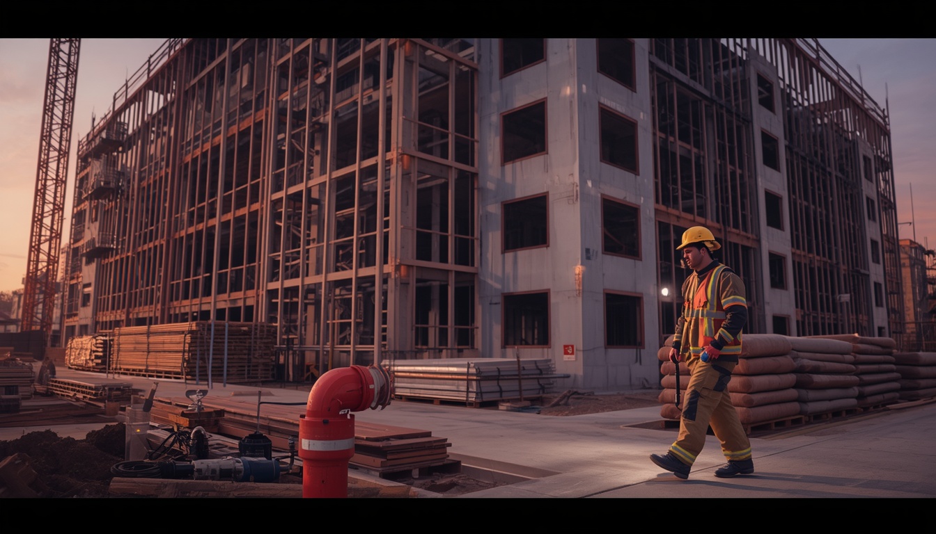
Construction, alteration, and demolition are among the highest-risk periods in the life of a building. The building’s fire protection systems are often incomplete, impaired, or yet to be installed. Combustible materials are staged, stored, and processed on site. Ignition sources (hot work, temporary heating, electrical equipment, smoking) are present throughout. The building may be occupied, partially occupied, or vacant, but in each case the fire risk is elevated and the protection is reduced.
The consequences are well documented. Fire protection that would normally contain a fire is not yet in place, the fuel load is often higher than it will be in the finished building, and sites are frequently unattended at night and on weekends, so fires grow before anyone notices. Several incidents illustrate the pattern: the 2009 fire at the Beijing Television Cultural Center complex, which included the unfinished Mandarin Oriental hotel and was ignited by fireworks set off at the site; the 2010 Shanghai high-rise apartment fire (58 fatalities), which began with welding sparks during exterior insulation renovation of an occupied building; and the 2017 Grenfell Tower fire in London, where earlier refurbishment of an occupied building changed how the exterior wall performed in fire. Large fires in wood-frame multifamily buildings under construction have also repeatedly shaped fire service tactics, insurance requirements, and code provisions.
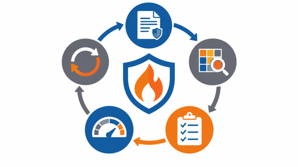
Fire safety during construction, alteration, and demolition is a distinct discipline. It is governed by NFPA 241 and IFC Chapter 33, supported by NFPA 51B (hot work), NFPA 25 (impairments), and NFPA 72 (fire alarm), regulated for workers by OSHA 29 CFR 1926, and shaped by the property insurer’s requirements. It requires a construction fire safety plan: a documented program that addresses ignition sources, fuel load, fire protection, egress, security, and emergency response throughout the project.
This article covers what makes construction fire safety different, the code framework, the construction fire safety plan, roles, temporary and permanent fire protection, hot work and impairment coordination, standpipes, water supply, and fire department access, egress, housekeeping, temporary heating, electrical and fuels, roofing and temporary enclosures, combustible construction, fire watch and security, emergency response, demolition, occupied-building alteration and phased occupancy, insurer requirements, and how to build a program that protects the building from groundbreaking to occupancy.
◆ Section 1: Why Construction Fire Safety Is Different
Construction fire safety is not a scaled version of occupied-building fire safety. It is a different risk profile with different controls.
| Factor | Occupied Building | Under Construction |
|---|---|---|
| Fire protection systems | Complete, operational, maintained | Incomplete, impaired, or not yet installed |
| Fire alarm | Complete, monitored | Incomplete, not monitored, or absent |
| Egress | Complete and marked | Temporary, obstructed, or missing |
| Compartmentation | Complete | Incomplete; openings and unfinished penetrations |
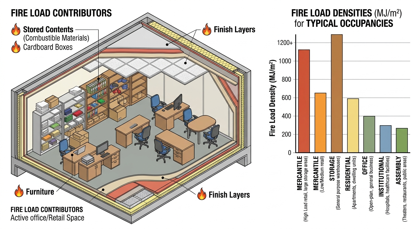
| Combustible loading | Controlled | High: materials, packaging, waste, and often the structure itself |
| Ignition sources | Controlled | Numerous: hot work, temporary heating, equipment, smoking, arson |
| Occupants | Trained and familiar | Workers, occupants, visitors; unfamiliar with the building |
| Building attendance | Staffed or monitored | Often unattended nights, weekends, and holidays |
| Fire department access | Established | Changing, obstructed |
| Water supply | Established | May be incomplete or temporary |
Key point: Construction fire safety is riskier than occupied-building fire safety because the protection is reduced while the ignition sources and fuel load are increased. The controls must compensate for this imbalance.
Key Article: Article 143 — Impairment Management and Fire Watch Procedures (NFPA 25)
Pro Tip: The first question in any construction fire safety plan should be: “What protection exists today, and what does it not protect?” The answer changes week by week.
◆ Section 2: The Code Framework
Construction fire safety is regulated by overlapping codes and standards.
A. NFPA 241
NFPA 241 is the primary standard for safeguarding construction, alteration, and demolition operations. It addresses:
- The fire prevention program and the construction fire safety plan
- Responsibilities of the owner, the contractor, and the fire prevention program manager
- Hot work controls, housekeeping, and waste management
- Temporary heating, electrical safety, and flammable liquids
- Fire department access and water supply
- Standpipe, sprinkler, and extinguisher requirements during construction
- Fire watch and site security
- Roofing operations and temporary enclosures
- Demolition-specific requirements
- Protection of adjacent properties
B. IFC Chapter 33 and NFPA 1 Chapter 16
IFC Chapter 33 is the code-enforceable version in IFC jurisdictions; NFPA 1 Chapter 16 plays the same role in NFPA 1 jurisdictions. They address the fire safety program and its designated superintendent or manager, owner and contractor responsibilities, fire protection systems and water supply during construction, access for firefighting, means of egress, precautions against fire spread, hot work, fire watch, and demolition. Note that the IFC uses the term fire prevention program superintendent where NFPA 241 uses fire prevention program manager; the role is the same.
C. IBC Chapter 33
IBC Chapter 33 (Safeguards During Construction) addresses the building-code side of construction safety, including fire extinguishers, temporary stairways and maintenance of means of egress, standpipes that must be installed as construction progresses, sprinkler installation, and water supply for firefighting.
D. OSHA 29 CFR 1926
OSHA regulates worker protection on construction sites. Subpart F (1926.150 through 1926.155) covers the fire protection program, fire prevention, flammable liquids, LP-gas, and temporary heating devices. Subpart T (1926.850 through 1926.860) covers demolition. OSHA also requires adequate means of egress for workers and a means of alerting employees to fire. OSHA 29 CFR 1910.157 applies to general-industry operations, such as an occupied building continuing to operate during alteration.
E. Supporting Standards
| Standard | Scope |
|---|---|
| NFPA 51B | Hot work fire prevention |
| NFPA 25 | Inspection, testing, maintenance, and impairment of water-based systems |
| NFPA 72 | Fire alarm system installation, testing, and impairments |
| NFPA 14 | Standpipe and hose systems |
| NFPA 13 | Sprinkler systems |
| NFPA 30 | Flammable and combustible liquids |
| NFPA 58 | LP-gas cylinders and heaters |
| NFPA 701 | Flame-resistant tarps, sheeting, and temporary coverings |
| Insurer requirements | Often stricter than code |
Key point: Construction fire safety is governed by NFPA 241 (standard), IFC Chapter 33 (code), IBC Chapter 33 (building code), OSHA 1926 (worker protection), and supporting standards. The most restrictive applicable requirement governs.
Pro Tip: In jurisdictions that adopt the IFC, Chapter 33 is the enforceable requirement and NFPA 241 is the technical basis. Cite both in the construction fire safety plan.
◆ Section 3: The Construction Fire Safety Plan
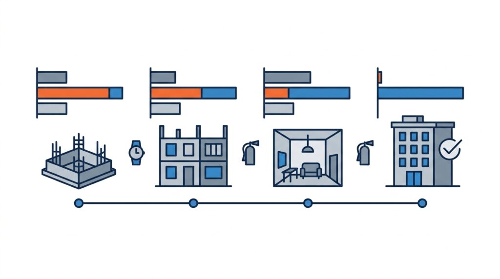
NFPA 241 requires a fire prevention program for construction, alteration, and demolition operations, and the AHJ may require a written, site-specific plan. The IFC likewise requires a fire safety program for construction and demolition sites. Whatever the minimum, the best practice is a written construction fire safety plan for every project, scaled to its size and risk. The plan is the central document of the program.
A. When a Written Plan Is Expected
| Source | Typical Trigger |
|---|---|
| NFPA 241 | Fire prevention program for all operations; written plan where required by the AHJ |
| IFC Chapter 33 | Fire safety program for construction and demolition; written plan where required by the fire code official |
| Local amendments | May set specific thresholds (height, area, combustible construction, demolition) |
| Insurer | Often required regardless of code |
The plan should be prepared before construction begins and updated as the project progresses.
B. Plan Content
| Element | Content |
|---|---|
| Project description | Scope, duration, phases, occupancy |
| Site plan | Layout, access roads, hydrants, water supply, staging, temporary facilities |
| Fire protection | Existing systems, temporary systems, impairments, status by phase |
| Hot work | Permit program, designated areas |
| Housekeeping and smoking | Waste management, combustible storage, smoking areas |
| Temporary heating, electrical, and fuels | Equipment, fuel storage, battery charging, safety |
| Roofing and temporary enclosures | Torch-applied roofing, scaffold sheeting, tarps |
| Means of egress | Temporary egress, exit signage, lighting |
| Fire department access | Routes, hydrants, FDC, standpipes, Knox box |
| Emergency response | Notification, evacuation, accountability, fire department coordination |
| Fire watch, patrol, and security | Schedule, responsibilities, site access control |
| Training | Worker orientation, fire extinguisher training |
| Demolition-specific | Utilities, structural hazards, dust, asbestos |
| Occupied-building alteration | Separation, notification, egress, compartmentation |
C. Fire Protection Status Matrix
The most useful single tool in the plan is a phase-by-phase status matrix. An illustrative example for a multistory building:
| Phase | Permanent Protection in Service | Temporary or Interim Protection | Compensating Measures |
|---|---|---|---|
| Site work and foundations | None | Access road, hydrant or temporary water supply, extinguishers | Site security and patrol |
| Structure rising | Standpipe extended to within one floor of the highest secured floor | Temporary lit stairway, marked FDC, extinguishers at hot work | Hot work permits, fire watch, nightly patrol |
| Enclosure and rough-in | Sprinklers installed progressively; partial zones in service | Temporary alarm or manual notification, extinguishers | Fire watch for impaired zones, daily egress walk |
| Finishes and commissioning | Systems in acceptance testing; some zones out of service | Temporary alarm in untested zones | Impairment coordinator, fire watch, fire department notification |
| Turnover | Full systems accepted | None | Final inspection and handover to building fire safety plan |
D. Plan Updates
The plan is a living document. It should be updated at each phase transition and whenever the fire protection status, hot work scope, water supply, access, or hazards change.
Key point: The construction fire safety plan is not a document to be filed and forgotten. It is the operational plan for the project’s fire safety, and it must reflect current conditions.
Key Article: Article 141 — Fire Safety Management Systems and ISO 31000 Alignment
Pro Tip: Review the plan at every project meeting. The most common failure is a plan that was accurate at the start of the project and never updated.
◆ Section 4: Roles and Responsibilities
Construction fire safety involves multiple parties. The roles must be defined in the plan.
A. Owner
- Owns the fire safety outcome and ensures the plan is prepared
- Provides resources for fire protection and designates the fire prevention program manager
- Coordinates with the AHJ and insurer
- Ensures the contractor complies
B. Contractor
- Implements the plan and manages subcontractors
- Manages hot work, impairments, and housekeeping
- Trains workers and reports incidents
C. Fire Prevention Program Manager (IFC: Program Superintendent)
NFPA 241 and the IFC call for a designated individual responsible for the fire prevention program through completion of the project. The role is often filled by the contractor’s safety officer or a designated fire safety professional. Responsibilities include:
- Developing and implementing the construction fire safety plan
- Coordinating with the fire department and the insurer
- Supervising hot work and fire watch
- Conducting inspections and training workers
- Maintaining records
D. Subcontractors
Comply with the plan, manage their own hot work, maintain housekeeping in their areas, train their workers, and report incidents.
E. AHJ and Fire Department
Review and approve the plan where required, inspect during construction, conduct pre-incident planning, respond to fires, and may impose additional requirements.
F. Insurer
May impose requirements beyond code, inspect during construction, and require specific protection measures.
Key point: Construction fire safety is a shared responsibility. The owner is ultimately accountable, the contractor implements, and the fire prevention program manager coordinates.
Pro Tip: Name the fire prevention program manager, and a deputy, in the plan. An unnamed role is an unassigned role.
◆ Section 5: Fire Protection During Construction
The fire protection available during construction changes week by week. The plan must address what protection exists at each phase.
A. Existing Systems
If the building has existing fire protection (alteration or renovation), keep the systems in service wherever possible. When impairment is necessary, the impairment process applies (see Section 7 and Article 143).
B. New Systems Under Construction
New systems should be placed in service as soon as practicable, progressing floor by floor or zone by zone. The plan should specify which systems will be in service at which phase, the testing and acceptance requirements for each, and the interim protection until each is in service.
C. Temporary Fire Protection
Where permanent protection is not yet available, temporary protection may be required:
| Temporary Protection | Application |
|---|---|
| Temporary standpipe | Provides fire department water supply on upper floors during construction |
| Temporary sprinklers | Provides automatic suppression in critical or high-value areas |
| Temporary fire alarm or manual notification | Provides detection and a means to alert workers (OSHA requires a means of alerting employees) |
| Temporary water supply | Provides water for firefighting |
| Fire watch | Provides human detection and response |
| Fire extinguishers | Provides first-aid firefighting |
D. Fire Extinguishers
Extinguishers must suit the hazards present:
| Hazard | Extinguisher Type |
|---|---|
| Ordinary combustibles | Class A (water, foam, multipurpose dry chemical) |
| Flammable liquids | Class B (foam, CO2, dry chemical) |
| Energized electrical equipment | Class C rating (CO2, dry chemical) |
| Combustible metals | Class D (special dry powder) |
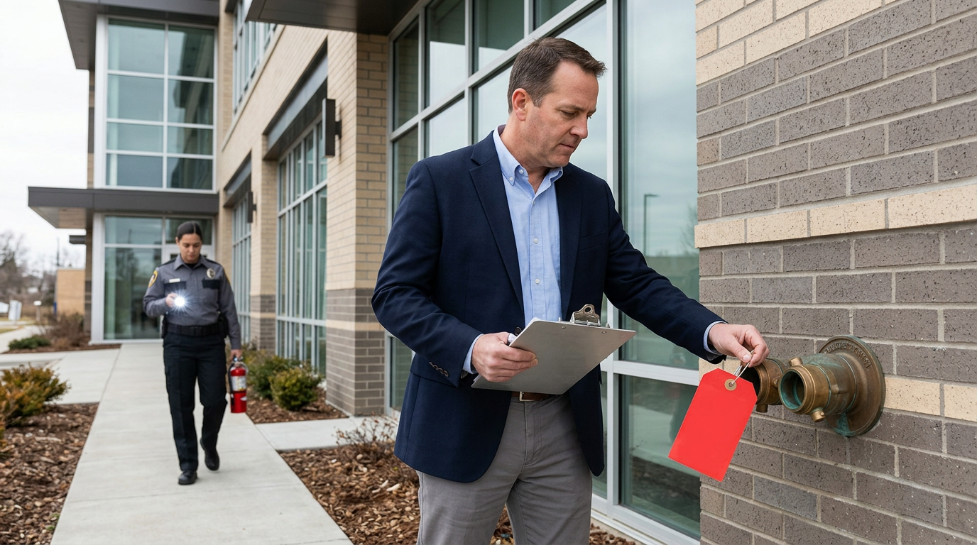
OSHA 29 CFR 1926.150 sets baseline requirements: at least one extinguisher rated not less than 2-A for each 3,000 square feet of protected building area (or major fraction), with travel distance to the nearest extinguisher not exceeding 100 feet; and an extinguisher rated not less than 10-B within 50 feet of any location where more than 5 gallons of flammable or combustible liquid or 5 pounds of flammable gas is in use. Extinguishers should also be placed at hot work locations, near temporary heating equipment, at each floor near stairways, and at accessible points throughout the site. Workers expected to use them need training, and the extinguishers must be inspected and kept charged.
Key point: Fire protection during construction is a moving target. The plan must define what protection exists at each phase and what interim measures compensate for the gaps.
Key Article: Article 23 — Commercial Building Code Requirements for Fire Sprinkler Systems
Pro Tip: Keep the fire protection status matrix on the project’s common board and brief it at the weekly coordination meeting.
◆ Section 6: Hot Work Coordination
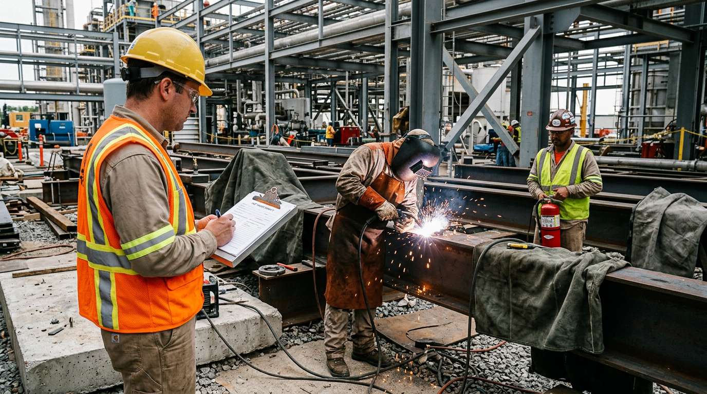
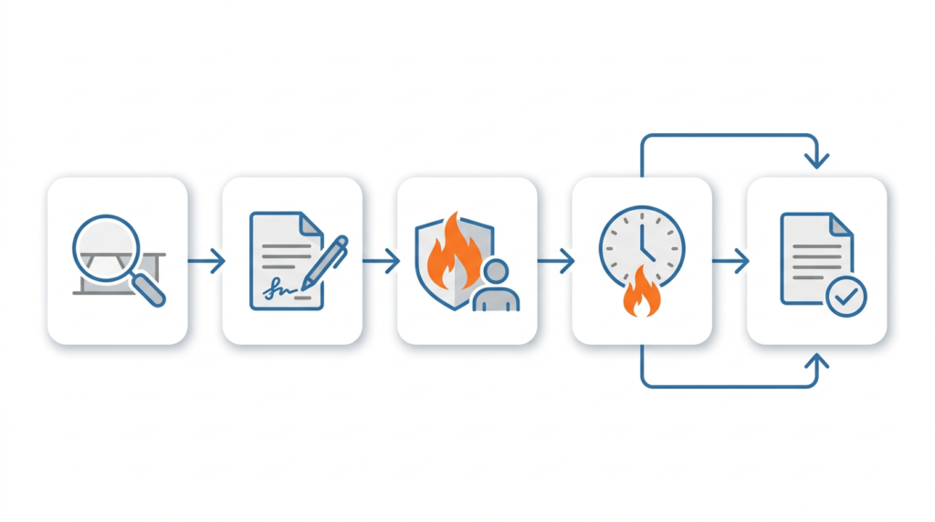
Hot work is one of the leading causes of construction fires, and it is the highest-risk combination on a site: ignition source, fuel load, and reduced fire protection. The hot work permit program (Article 142) must be integrated with the construction fire safety plan.
A. Hot Work During Construction
| Requirement | Detail |
|---|---|
| Permit program | Required for hot work outside designated areas |
| Permit authority | The contractor’s fire prevention program manager or a designated Permit Authorizing Individual (PAI) |
| Coordination with building | The building owner or operator must approve hot work in occupied buildings |
| Fire watch | Required during hot work per NFPA 51B and IFC Chapter 35 |
| Post-work watch and monitoring | Required per NFPA 51B and the adopted IFC; minimum durations differ by edition and insurers often require 60 minutes or more |
| Contractor compliance | Subcontractors must comply with the program |
B. Designated Hot Work Areas
Where possible, designate an area free of combustibles and approved for repeated hot work, such as a prefabrication or cutting area. Hot work in designated areas can proceed without an individual permit, subject to controls.
C. Hot Work in Occupied Buildings
When hot work occurs in an occupied building, the building’s hot work program and the construction fire safety plan must be coordinated. The building’s PAI should issue or countersign the permit.
D. Special Hot Work Concerns on Construction Sites
- Welding or cutting near exterior insulation, foam plastics, wood framing, scaffold sheeting, or combustible membranes
- Cutting and welding in shafts, voids, and above ceilings where sparks travel unseen
- Torch-applied roofing (see Section 12)
- Cutting of scrap and steel during demolition (see Section 16)
Key point: The hot work program must be integrated with the construction fire safety plan, not run in parallel.
Key Article: Article 142 — Hot Work Permit Programs and Procedures
Pro Tip: Require the hot work permit to reference the current fire protection status. The permit is not valid if the required protection is not in place.
◆ Section 7: Impairment Coordination
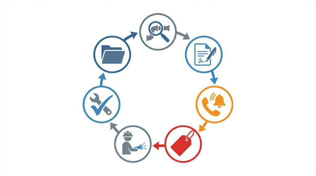
Construction frequently requires impairment of existing fire protection systems: sprinklers in the work area, detection in the work area, or systems being modified. The impairment process (Article 143) applies.
A. Impairments During Construction
| Situation | Governing Requirement |
|---|---|
| Sprinkler relocation or modification | NFPA 25 Chapter 15 |
| Detection or alarm modification | NFPA 72 (impairment and testing provisions) |
| Standpipe modification | NFPA 25 Chapter 15 (NFPA 14 governs installation) |
| Fire pump work | NFPA 25 Chapter 15 |
| Water supply interruption | NFPA 25 Chapter 15 and utility coordination |
B. The 10-Hour Rule During Construction
Under NFPA 25, where a system impairment is expected to exceed 10 hours in a 24-hour period, the impairment coordinator must arrange compensating measures: evacuation of the affected area, approved temporary fire protection, fire watch, or occupant notification. The IFC also requires a fire watch or other approved measures when required systems are out of service. These rules apply during construction. The fire watch for impairment may be the same as the construction fire watch, but its scope must match the impairment.
C. Cumulative Impairments
Construction often involves many impairments over a project. Track each individually, monitor cumulative out-of-service time, and notify the fire department, the monitoring company, and the insurer as required.
Key point: Construction creates impairments continuously. The impairment process must be managed as a routine part of construction fire safety, not as an exception.
Key Article: Article 143 — Impairment Management and Fire Watch Procedures (NFPA 25)
Pro Tip: Include the impairment log in the monthly status report. The log shows cumulative out-of-service time and the compensating measures for each impairment.
◆ Section 8: Standpipes, Water Supply, and Fire Department Access
Standpipes, water, and access are the fire department’s lifeline during construction. NFPA 241, IFC Chapter 33, and IBC Chapter 33 all address them. If they are not available, the fire department’s ability to fight a fire is severely limited.
A. Standpipe Requirements
Where a building will require standpipes, the model codes expect at least one standpipe to be installed for fire department use during construction, starting when construction reaches about 40 feet above the lowest level of fire department vehicle access, and extended as construction progresses to within one floor of the highest secured decking or flooring. Verify the threshold in your adopted edition.
| Requirement | Detail |
|---|---|
| Installation timing | As soon as the structure permits and no later than the code trigger height |
| Location | Within or adjacent to usable stairways, or as approved |
| Accessibility | Hose connections accessible to the fire department at all times |
| Marking | Clearly marked and identified, including the floor level |
| Testing | Tested per NFPA 14 before use |
| Extension | Extended as each floor is decked |
B. Water Supply
An approved water supply, temporary or permanent, should be available as soon as combustible materials arrive on site. Sources may include:
- Existing or new permanent hydrants
- Temporary hydrants
- On-site water storage
- Fire department pumper connections
The plan should specify the water supply for each phase and confirm its capacity and reliability. Underground water mains and hydrants should be installed and in service before combustible construction proceeds.
C. Fire Department Connection (FDC)
The FDC must be accessible and identified. If the FDC is not yet connected to the system, or the system is not yet in service, it should be clearly marked as such. Protect FDCs from damage by construction traffic and keep them free of stored materials.
D. Access for Firefighting
The IFC calls for approved vehicle access for firefighting to construction and demolition sites, including access to within a specified distance (commonly 100 feet) of temporary or permanent FDCs, by roads able to carry fire apparatus in all weather conditions.
- Keep access roads, gates, and turnarounds clear of deliveries, cranes, and parked vehicles
- Provide key access (for example, a Knox box) at site gates and building entries
- Post a site plan at the entrance showing hydrants, FDCs, standpipe locations, stairs, and hazards
- Notify the fire department when access or water supply is changed or interrupted
Key point: Water and access are the minimum conditions for a fire department response. They must be in place before the fuel arrives and must be maintained throughout the project.
Key Article: Article 111 — Standpipe and Hose System Design (NFPA 14)
Pro Tip: Coordinate standpipe installation and access routes with the fire department. They can advise on location, hose connection height, and timing.
◆ Section 9: Egress During Construction
Egress during construction is often temporary and inadequate. NFPA 241, IFC Chapter 33, IBC Chapter 33, and OSHA 1926 all address it.
A. Egress Requirements
| Requirement | Detail |
|---|---|
| Exit access | Clear path to exits at all times, not blocked by materials or equipment |
| Exit signage | Temporary signage where permanent signage is not yet installed |
| Emergency lighting | Temporary lighting where permanent lighting is not yet installed |
| Exit doors | Functional and unlocked from the inside; construction fences and hoarding must not trap workers |
| Stairways | Available, lit, and safe; the IBC expects a temporary lighted stairway for buildings under construction above roughly 50 feet or four stories, unless permanent stairs are erected as construction progresses |
| Floor openings and shafts | Guarded and not used as egress |
B. Egress Changes
Construction often changes egress paths. When egress is changed:
- Notify occupants (if occupied) and workers
- Post temporary signage
- Verify that the new path is clear and safe
- Update the plan and notify the fire department if access to exits or stairs is affected
C. Stairways, Hoists, and Tall Buildings
Stairways under construction may not be complete. If a stairway is not available for egress, an alternative must be provided and the fire department notified. On tall buildings, construction hoists and elevators are not egress. Workers must be able to leave upper floors by a protected stair, and rescue and firefighter access must be planned for.
Key point: Egress during construction is a life safety requirement, not a convenience. Workers and occupants must have a clear path to exit at all times.
Key Article: Article 123 — Exit Access, Exit, and Exit Discharge Explained
Pro Tip: Walk the egress path every day. Obstructions, locked doors, and missing signage are the most common egress failures during construction.
◆ Section 10: Housekeeping, Smoking, and Combustible Control
Housekeeping is one of the most effective fire prevention measures during construction, and one of the most frequently neglected.
A. Housekeeping Requirements
| Requirement | Detail |
|---|---|
| Waste removal | Waste removed at the end of each shift or daily |
| Combustible storage | Stored away from ignition sources and egress paths |
| Dust control | Combustible dust controlled and cleaned |
| Packaging | Packaging removed promptly |
| Scrap material | Scrap removed promptly |
B. Combustible Storage and Waste
Large quantities of combustible materials (lumber, packaging, insulation, pallets) create a high fuel load. The plan should specify designated storage areas, maximum quantities, separation from ignition sources and egress paths, separation from buildings, and protection of storage areas. Waste containers should be non-combustible where practical, emptied on a set schedule, and located away from the building. Burning waste on site should be prohibited.
C. Smoking
Smoking is a persistent ignition source on sites. The plan should prohibit smoking inside the building and in storage and fueling areas, and designate outdoor smoking areas with non-combustible receptacles, away from the structure and from combustible materials.
D. Oily Rags and Finishing Materials
Rags soaked with stains, oils, and solvents can self-heat and ignite. Store them in listed oily-waste cans or submerge them in water, and remove them from the building daily. Exposed foam plastic insulation and flammable adhesives, coatings, and finishes need controlled storage, ventilation, and elimination of ignition sources during application.
Key point: Housekeeping is a daily discipline, not a weekly cleanup. Small accumulations become large fire loads.
Pro Tip: Assign housekeeping responsibility by area. “Everyone’s responsibility” is no one’s responsibility.
◆ Section 11: Temporary Heating, Electrical, and Fuels
Temporary heating, electrical, and fuel-burning equipment are common ignition sources. OSHA 1926.154 and NFPA 241 set requirements for temporary heating devices.
A. Temporary Heating
| Equipment | Fire Risk | Controls |
|---|---|---|
| Propane or direct-fired heaters | Fuel leak, open flame, ignition of nearby combustibles | Listed equipment, clearances, ventilation, fuel storage per NFPA 58, no use in enclosures without adequate ventilation |
| Electric heaters | Overheating, electrical fault | Listed equipment, GFCI, clearances |
| Kerosene heaters | Fuel, open flame, carbon monoxide | Prohibited or restricted in many jurisdictions; verify |
| Salamanders and torpedo heaters | Open flame, hot surfaces, fuel | Clearances, ventilation, attendance, never near tarps or wood |
B. Temporary Electrical
| Equipment | Fire Risk | Controls |
|---|---|---|
| Temporary power | Overload, short circuit | Listed equipment, GFCI, adequate capacity |
| Extension cords | Damage, overload | Inspected, rated for the load, not used as permanent wiring |
| Temporary lighting | Overheating of lamps near combustibles | Listed equipment, guarded, clearances |
| Generators | Fuel, hot exhaust, carbon monoxide | Location outside, fuel storage, refueling only when cool |
C. Flammable Liquids and Gases
Fuels, solvents, and adhesives should be stored in approved containers and locations (NFPA 30, IFC Chapter 57, OSHA 1926.152). LP-gas cylinders should be stored outdoors, upright, secured, and away from ignition sources (NFPA 58, OSHA 1926.153). Refueling of equipment should be done in designated areas with the engine off and cool.
D. Battery Charging
Lithium-ion batteries for tools, lighting, and equipment are an increasing ignition source. Charge them in a designated area with non-combustible surfaces, away from egress and combustible storage, using manufacturer-approved chargers, and do not charge unattended overnight in the building.
Key point: Temporary equipment introduces ignition sources that will not exist in the finished building. The controls must be specified in the plan.
Pro Tip: Inspect temporary heating, electrical, and charging equipment daily. It is often moved, modified, and left unattended.
◆ Section 12: Roofing Operations and Temporary Enclosures
Two construction activities deserve their own controls because they combine heat, combustibles, and elevated or concealed spaces.
A. Roofing Operations
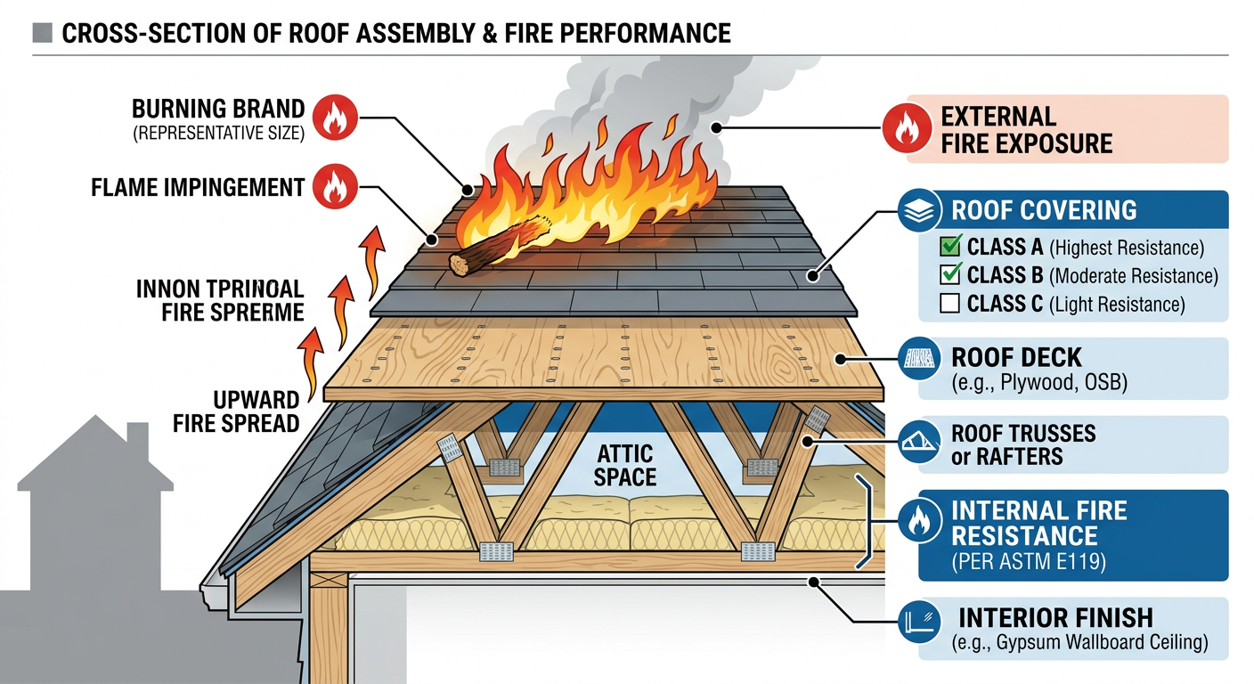
Torch-applied roofing and hot kettle operations (asphalt, tar) are leading causes of roof fires, often starting hours after the crew has left because heat has traveled into concealed spaces. NFPA 241 and the IFC address them. Controls include:
- Hot work permits and a trained, equipped fire watch
- Extinguishers on the roof at the work location
- Inspection of the work area, including adjoining concealed spaces and flashings, and a post-work watch lasting well beyond the end of the work
- Kettles placed on non-combustible surfaces away from the building where practical, and attended at all times
- Cold-applied or mechanically attached systems preferred where the design permits
B. Temporary Enclosures, Scaffold Sheeting, and Tarps
Weather protection, scaffold sheeting, netting, and tarps can carry fire up and across a building, as seen in the 2010 Shanghai fire. Use flame-resistant materials meeting NFPA 701 or the AHJ’s requirements, keep hot work and heaters away from them, and treat them as part of the fuel load. Enclosed work areas also need ventilation and a means of egress through the enclosure.
Key point: Roofing and temporary enclosures are common starting points and spread paths. Control them as hot work and as fuel.
Pro Tip: Require flame-resistance certificates for tarps and sheeting in the submittal package, and keep them on file.
◆ Section 13: Combustible Construction (Wood Frame and Mass Timber)
Buildings of combustible construction are the most vulnerable while under construction. Framing is exposed and unprotected, sprinklers and fire-resistance-rated finishes are not yet in place, and the structure itself can sustain the fire. Fires in large wood-frame multifamily projects have destroyed buildings and damaged neighbors from the fire’s radiant heat and flying brands.
A. Why the Risk Is Higher
- Exposed combustible framing, sheathing, and weather barriers
- Long periods without sprinklers in service
- Concealed spaces and unprotected vertical openings
- Heavy hot work, and temporary heating in winter
- Exposure to adjacent buildings, which can be significant
B. Additional Controls
- Install sprinklers and standpipes as early as the construction sequence permits, and keep water supply in service
- Recent IFC editions include fire watch and related provisions for certain combustible-construction projects; verify your adopted edition and local amendments
- Provide fire watch and patrols during non-working hours
- Control hot work strictly, limit simultaneous trades in the same area
- Install firestopping and fire-resistant elements as the sequence permits
- Evaluate exposure to adjacent properties and agree on protection with neighbors and the fire department
- Consider temporary detection or monitored sensors on large combustible projects
C. Mass Timber
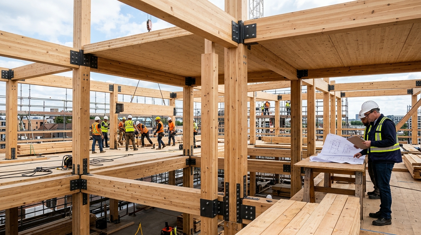
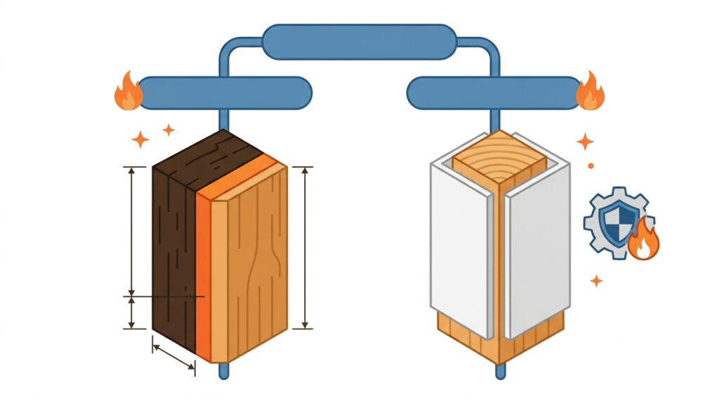
Mass timber projects (CLT, glulam) add the question of whether exposed timber is required to be protected during construction, and how long it may remain exposed. The IBC type IV-A, IV-B, and IV-C requirements, protection of exposed timber from weather and fire, and early sprinkler installation should be addressed in the plan. See the article on Mass Timber and Engineered Wood Fire Safety.
Key point: The more combustible the structure, the earlier the water, the stricter the hot work, and the stronger the watch must be.
Pro Tip: Hold a pre-construction meeting with the fire department and the insurer for any combustible project of three stories or more.
◆ Section 14: Fire Watch, Patrol, and Site Security
Fire watch and patrol during construction serve a different purpose than in an occupied building. Sites are often unoccupied when fires start (at night, on weekends, and during holidays), and some fires are deliberately set.
A. Fire Watch During Construction
| Situation | Fire Watch Requirement |
|---|---|
| Hot work | Per NFPA 51B (during and after work) |
| Impairment | Per NFPA 25 and Article 143 |
| Non-working hours | As required by the AHJ, the insurer, or the plan |
| High hazard or combustible construction | As required by the AHJ, the IFC edition, or the plan |
B. Patrol Requirements
Many plans require periodic patrols during non-working hours to detect fires early, check for hot work residue, and verify that the site is secure. Frequency is set by the AHJ, the insurer, the plan, or local code. Patrols should use a documented route and check-in points, and patrollers should be able to report a fire immediately.
C. Fire Watch Qualifications
Fire watch personnel must be trained and equipped, as in occupied buildings. The role is to watch for fire, notify the fire department, and respond if safe to do so. A fire watch should not have other duties that distract from watching.
D. Site Security
Vandalism, theft, and arson are significant causes of fires at construction sites. Perimeter fencing, controlled access, lighting, and where warranted, monitored cameras or guards reduce both unauthorized entry and ignition. Secure combustible storage and fueling areas, and keep ladders and scaffolds restricted after hours.
Key point: Construction sites are vulnerable when unoccupied. Fire watch, patrol, and security are the primary means of early detection and prevention during non-working hours.
Pro Tip: Equip the fire watch with a site plan, a list of hot work locations, a charged communication device, and contact numbers for the fire department and the site supervisor.
◆ Section 15: Emergency Response and Fire Department Coordination
Even a strong prevention program must assume a fire will occur. Workers need to know how to raise the alarm and leave, and the fire department needs to know what it will find.
A. Notification and Alarm
| Element | Detail |
|---|---|
| Means of alerting workers | Air horns, radios, temporary alarm, or the building system where in service; audible across the site |
| Reporting a fire | Posted emergency numbers, working phones or radios at each work area, and a clear address and site entrance for dispatch |
| Alarm system status | If the building alarm is not monitored or is impaired, a site-specific method must notify the fire department |
B. Evacuation and Accountability
The plan should define evacuation routes, muster points, and a headcount method. Subcontractor sign-in and daily rosters make accountability possible. Evacuation drills should be held at project start for the workforce and repeated as phases change.
C. Fire Department Coordination
- Hold a pre-construction meeting to review the site plan, hazards, access, water supply, and the fire protection status matrix
- Provide the fire department with updates at each major phase, and with 24-hour contacts for the project
- Invite the fire department to walk the site periodically for pre-incident planning
- Notify the fire department and the insurer when systems or water are impaired, or access is changed
Key point: In an emergency, workers must hear the alarm, know where to go, and be counted, and the fire department must know what is protected.
Pro Tip: Post a one-page emergency sheet at every site entrance and stair: site address, emergency numbers, muster point, and the location of hydrants, FDCs, and standpipes.
◆ Section 16: Demolition-Specific Hazards
Demolition presents hazards that construction and alteration do not.
A. Demolition Fire Hazards
| Hazard | Detail |
|---|---|
| Fire protection systems removed or impaired | Systems may be partially or fully removed as demolition progresses |
| Combustible debris | Demolition debris is a high fire load |
| Utilities | Gas, electric, and water may be live |
| Structural instability | Fire can weaken remaining structure and endanger firefighters |
| Dust | Combustible dust from demolition and cutting |
| Asbestos and hazardous materials | Fire can release hazardous materials |
| Adjacent buildings | Fire can spread to adjacent buildings |
| Cutting torches | Scrap and steel cutting generates sparks and slag |
B. Demolition Requirements
NFPA 241, IFC Chapter 33, and OSHA Subpart T address demolition. Key elements include:
- An engineering survey by a competent person before work begins, and a survey for asbestos and other hazardous materials as required by environmental regulations
- Shutting off, capping, or controlling utilities before demolition, and coordinating with utility companies
- Keeping standpipes and sprinklers in service as long as practicable, and removing them in step with the demolition
- Removing combustible debris promptly and keeping it away from the structure
- Controlling hot work and providing fire watch
- Protecting adjacent buildings, including openings and exposures
- Providing for fire department access and water supply throughout
C. Blasting and Implosion
Explosive demolition is a specialized method governed by separate blasting regulations and licensed specialists. The fire service and the AHJ should be involved in planning, and fire protection should be in place during and after the event.
Key point: Demolition removes the building’s fire protection while leaving the hazards. The plan must address demolition-specific risks.
Pro Tip: Coordinate demolition sequencing with the fire department. They can advise on access, water supply, and building condition for firefighter safety.
◆ Section 17: Occupied-Building Alteration and Phased Occupancy
Alteration of an occupied building is a special case: the building is occupied, but it is also under construction.
A. The Occupied-Building Challenge
| Challenge | Detail |
|---|---|
| Occupants present | Workers and occupants share the building |
| Fire protection impaired | Systems may be impaired for alteration |
| Egress disrupted | Egress paths may change |
| Compartmentation breached | Fire barriers and smoke barriers may be opened |
| Noise, dust, vibration | Affect occupants and may trigger false alarms |
| Emergency response | Coordination between construction and occupancy |
B. Requirements for Occupied-Building Alteration
| Requirement | Detail |
|---|---|
| Construction fire safety plan | Addresses both construction and occupancy |
| Fire protection | Systems maintained as much as possible; impairment process for necessary outages |
| Egress | Maintained or a temporary alternative provided |
| Compartmentation | Fire barriers maintained or temporarily protected; penetrations firestopped as work proceeds |
| Detection | Detectors protected from dust only with approved covers, removed promptly at end of each shift |
| Notification | Occupants notified of construction activities and changes |
| Fire watch | As required by the AHJ or plan |
| Separation | Physical separation between construction and occupied areas |
C. Phased Occupancy and the Transition to Permanent Protection
New buildings are sometimes occupied in phases while construction continues elsewhere. NFPA 241, the building code, and the AHJ will typically require that the occupied portion have complete and accepted fire protection, egress, and fire alarm, and that the construction areas be separated and protected. Before any portion is occupied:
- Complete acceptance testing of sprinklers, standpipes, fire alarm, emergency lighting, and smoke control serving the occupied area
- Obtain the required temporary or partial certificate of occupancy
- Verify the separation between occupied and construction areas
- Hand over the building’s fire safety plan, and keep the construction plan in effect for the remaining work
D. Coordination
Occupied-building alteration requires coordination between the building owner, the building operator, the contractor, the fire prevention program manager, the AHJ, and the occupants.
Key point: Occupied-building alteration is the most complex construction fire safety scenario. Both the construction fire safety plan and the building’s fire safety plan must be coordinated and current.
Key Article: Article 76 — How to Design a Fire Safety Strategy for Existing Buildings (Retrofits)
Pro Tip: Hold a coordination meeting before each phase of alteration. The meeting ensures that the construction and occupancy plans remain aligned.
◆ Section 18: Insurer Requirements
Property insurers often impose stricter requirements than the code for construction fire safety.
A. Common Insurer Requirements
| Requirement | Detail |
|---|---|
| Construction fire safety plan | Some insurers require a plan even where code does not |
| Fire watch | Some insurers require fire watch during non-working hours |
| Hot work procedures | Some insurers require specific hot work procedures and post-work watch durations |
| Impairment notification | Some insurers require notification before any impairment |
| Temporary protection | Some insurers require temporary sprinklers, standpipes, or detection |
| Contractor qualifications | Some insurers require contractor insurance and safety records |
| Inspections | Some insurers inspect during construction |
B. The Consequence of Non-Compliance
Failure to follow insurer requirements can affect coverage after a fire. Depending on the policy, the insurer may deny or reduce a claim, increase premiums, or cancel coverage.
Key point: Where the insurer’s requirement is stricter than the code, follow the stricter one. The insurer is the party that will pay for the fire.
Key Article: Article 149 — Insurance Requirements and Fire Protection Credits (planned)
Pro Tip: Obtain the insurer’s construction fire safety requirements in writing before construction begins and incorporate them into the plan.
◆ Section 19: Inspections, Records, and Documentation
Construction fire safety generates records that demonstrate the program was implemented. If a fire occurs, they are the first thing the investigator will request.
A. Inspections
The fire prevention program manager should conduct and document daily walk-throughs (egress, housekeeping, hot work areas, temporary heating, extinguishers), weekly formal inspections, and a review at each phase transition. Findings should have a named owner and a due date, and open items should be reviewed at the project meeting.
B. Records to Maintain
| Record | Content |
|---|---|
| Construction fire safety plan | Current plan with updates |
| Plan updates | Each revision with date and reason |
| Hot work permits | Per Article 142 |
| Impairment records | Per Article 143 |
| Fire watch logs | Patrol times, areas checked, observations |
| Inspection records | Daily, weekly, and periodic inspections |
| Training records | Worker orientation, extinguisher training |
| Incident reports | Fires, near-misses, stop-work events |
| Fire department visits | Inspections, walkthroughs, pre-incident planning |
| Insurer inspections | Reports and follow-up |
C. Retention Period
Retention requirements vary. As a practical standard:
- Retain construction records for at least the duration of the project plus the applicable statute of limitations
- Retain records related to a fire, incident, claim, or litigation until the matter is resolved
- Retain records required by the AHJ or insurer per their requirements
Pro Tip: Maintain the records in a single project file accessible to the AHJ, the insurer, and the fire investigator, and hand the relevant records over to the owner at turnover.
◆ Section 20: Common Mistakes and How to Avoid Them
| Mistake | Why It’s a Problem | How to Fix |
|---|---|---|
| No construction fire safety plan | Fire protection not planned | Prepare the plan before construction begins |
| Plan prepared but not implemented | Document filed, practice unchanged | Walk the site daily and enforce the plan |
| Plan not updated | Plan no longer matches conditions | Update at each phase and when conditions change |
| Program manager not named | Role unassigned | Name the individual and a deputy in the plan |
| Hot work outside the program | Uncontrolled ignition source | Integrate hot work permits with the plan |
| Impairments treated as exempt | Building unprotected | Apply the NFPA 25 impairment process |
| Standpipes and water installed late | Fire department cannot fight a fire | Install early; coordinate with the fire department |
| Egress obstructed | Life safety risk | Maintain egress; walk the path daily |
| Housekeeping neglected | Fire load accumulates | Assign responsibility by area |
| Smoking uncontrolled | Persistent ignition source | Prohibit in the building; designate outdoor areas |
| Temporary heating unmanaged | Ignition source | Inspect daily; listed equipment; clearances |
| Tarps and sheeting not fire-resistant | Fire spreads on the exterior | Specify NFPA 701 materials; control hot work nearby |
| Fire watch and security not provided | Fires undetected when site is unoccupied | Provide fire watch, patrol, and access control |
| Demolition hazards underestimated | Protection removed while hazards remain | Address demolition-specific risks |
| Occupied-building alteration not coordinated | Two plans, one building | Coordinate construction and occupancy plans |
| Insurer requirements not followed | Coverage affected after a fire | Obtain and incorporate insurer requirements |
| Records not retained | Cannot demonstrate compliance | Maintain a project file |
Key point: The most common failure in construction fire safety is the gap between the plan and the practice.
Pro Tip: Walk the site every day. The plan is only effective if the conditions on site match the plan.
◆ Section 21: Design Checklist
| Item | Status | Notes |
|---|---|---|
| Construction fire safety plan prepared | ☐ | Before construction begins |
| Plan updated at each phase | ☐ | Phase transitions, condition changes |
| Fire prevention program manager named | ☐ | In the plan, with a deputy |
| Owner, contractor, subcontractor responsibilities defined | ☐ | In the plan |
| Fire protection status matrix documented per phase | ☐ | What is in service, what is impaired |
| Temporary fire protection specified | ☐ | Standpipe, sprinkler, alarm, water supply |
| Fire extinguishers specified | ☐ | By hazard, location, and OSHA 1926.150 |
| Hot work program integrated | ☐ | Permit, fire watch, post-work watch |
| Impairment process applied | ☐ | Per NFPA 25 Chapter 15 and Article 143 |
| Standpipes installed and extended early | ☐ | Coordinated with fire department |
| Water supply and access confirmed | ☐ | Hydrants, temporary supply, roads, Knox box |
| Egress maintained | ☐ | Paths, signage, lighting, temporary stairs |
| Housekeeping and smoking program | ☐ | Waste removal, storage, designated smoking areas |
| Temporary heating, electrical, fuels, and charging | ☐ | Listed equipment, clearances, inspection |
| Roofing and temporary enclosure controls | ☐ | Torch-applied roofing, NFPA 701 sheeting |
| Combustible construction measures | ☐ | Early sprinklers, strict hot work, exposure protection |
| Fire watch, patrol, and security | ☐ | Schedule, qualifications, log, fencing |
| Emergency response and evacuation | ☐ | Alarm, muster, accountability, emergency sheet |
| Demolition-specific hazards addressed | ☐ | Survey, utilities, debris, adjacent buildings |
| Occupied-building alteration and phased occupancy coordinated | ☐ | Construction and occupancy plans; acceptance testing |
| Insurer requirements incorporated | ☐ | In writing |
| Inspections and records maintained | ☐ | Project file |
| Fire department coordination | ☐ | Pre-construction, during construction |
◆ Section 22: Conclusion
Fire safety during construction, alteration, and demolition is a distinct discipline. The building’s fire protection is reduced, the fuel load is increased, the ignition sources are numerous, and the people on site may be workers, occupants, or both. The controls must compensate for this imbalance.
The framework is NFPA 241 (standard), IFC Chapter 33 (code), and IBC Chapter 33 (building code), supported by NFPA 51B (hot work), NFPA 25 (impairments), NFPA 72 (fire alarm), OSHA 29 CFR 1926, and the insurer’s requirements. The construction fire safety plan is the central document. It must be prepared before construction begins, updated as the project progresses, and implemented every day.
The most common failure is the gap between the plan and the practice. The plan is prepared, but the fire protection is not in place, the hot work is not controlled, or the housekeeping is neglected.
Key Takeaways:
- Construction fire safety is riskier than occupied-building fire safety because protection is reduced while ignition sources and fuel load are increased.
- NFPA 241, IFC Chapter 33, IBC Chapter 33, and OSHA 1926 form the primary framework; follow the most restrictive requirement.
- A written construction fire safety plan is best practice for every project and must be updated as conditions change.
- The fire prevention program manager is the central role for implementing the plan.
- Fire protection during construction is a moving target; a phase-by-phase status matrix keeps it visible.
- Hot work is one of the leading causes of construction fires; integrate the hot work program with the plan.
- Construction frequently requires impairment of existing systems; apply NFPA 25 Chapter 15.
- Standpipes, water supply, and fire department access are the fire department’s lifeline; install them early.
- Egress must be maintained at all times, with temporary signage, lighting, and stairs.
- Housekeeping, smoking control, and combustible storage are daily disciplines.
- Temporary heating, electrical equipment, fuels, and battery charging are common ignition sources; inspect daily.
- Roofing operations and temporary enclosures are common starting points and spread paths.
- Combustible construction needs earlier water, stricter hot work, and stronger watch.
- Fire watch, patrol, and security are essential during non-working hours.
- Emergency response depends on alarm, evacuation, accountability, and fire department familiarity with the site.
- Demolition removes the building’s fire protection while leaving the hazards.
- Occupied-building alteration and phased occupancy require coordinated plans and accepted protection.
- Insurer requirements often exceed code; follow the stricter one.
- Records must be retained to demonstrate compliance.
Take Action Today:
- Confirm a construction fire safety plan is prepared before construction begins.
- Name the fire prevention program manager and a deputy in the plan.
- Define owner, contractor, and subcontractor responsibilities.
- Document the fire protection status at each phase.
- Specify temporary fire protection for phases without permanent systems.
- Integrate the hot work program with the plan.
- Apply the impairment process for any system out of service.
- Confirm standpipes, water supply, and fire access are in place before combustibles arrive.
- Walk the egress path daily.
- Assign housekeeping responsibility by area and designate smoking areas.
- Inspect temporary heating, electrical, and charging equipment daily.
- Control roofing operations and require flame-resistant temporary enclosures.
- Provide fire watch, patrol, and security per the plan and AHJ.
- Post an emergency sheet and agree on the evacuation and muster plan.
- Address demolition-specific hazards in the plan.
- Coordinate occupied-building alteration and phased occupancy with the building’s fire safety plan.
- Obtain the insurer’s construction fire safety requirements in writing.
- Maintain the project fire safety file and coordinate with the fire department before and during construction.
Continue Reading from Our Series:
-
Related guide: Article 143 — Impairment Management and Fire Watch Procedures (NFPA 25)
-
Related guide: Article 142 — Hot Work Permit Programs and Procedures
-
Read more: Article 76 — How to Design a Fire Safety Strategy for Existing Buildings (Retrofits) (planned)
About This Guide: This article is part of a series on commercial building fire safety, written for facility managers, architects, and code officials. It references model codes and standards for educational purposes. Always consult your local AHJ for project-specific requirements.