
IMPORTANT DISCLAIMER: This guide references NFPA 101, Life Safety Code, including Chapter 5 (Performance-Based Option); NFPA 92, Standard for Smoke Control Systems; the International Building Code (IBC), including Section 104.11 (Alternative Materials, Design and Methods of Construction and Equipment; verify the section number in the edition your jurisdiction has adopted); the International Fire Code (IFC); the SFPE Engineering Guide to Performance-Based Fire Protection; the SFPE Handbook of Fire Protection Engineering; ASTM E1355 (Standard Guide for Evaluating the Predictive Capability of Deterministic Fire Models); ASTM E1472 (Standard Guide for Documenting Computer Software for Fire Models); ASTM E1591 (Standard Guide for Obtaining Data for Deterministic Numerical Fire Models); ISO 16730 (Fire Safety Engineering: Assessment, Verification and Validation of Calculation Methods); ISO 13571 (Life-Threatening Components of Fire: Guidelines for the Estimation of Time to Compromised Tenability); ISO/TR 16738 (Fire-Safety Engineering: Technical Information on Methods for Evaluating Behaviour and Movement of People); and the documentation requirements of the Authority Having Jurisdiction (AHJ). Fire and egress models are tools that require qualified operators and expert interpretation. Model results are only as good as the inputs, assumptions, and validation. Software features, capabilities, and limitations cited here are current as of publication and may change. This guide is a starting point only. Always verify the requirements applicable to your project with your AHJ and a qualified fire protection engineer.
Performance-based fire engineering depends on models. The fire model predicts how a fire will grow and how smoke will spread; the egress model predicts how occupants will evacuate. Together, they allow the engineer to compare the available safe egress time (ASET) to the required safe egress time (RSET) and to demonstrate that the design achieves the performance objectives.
The software that performs these calculations has evolved significantly over the past three decades. The Fire Dynamics Simulator (FDS), developed by the National Institute of Standards and Technology (NIST), has become the de facto standard for computational fluid dynamics (CFD) fire modeling. CFAST, also developed by NIST, is widely used for zone modeling. Pathfinder, STEPS, and buildingEXODUS are among the most widely used egress models. Each has different capabilities, different limitations, and different appropriate applications.
Fire and egress modeling is the discipline of selecting the right model for the problem, using it correctly, validating the results, and interpreting the output. It is not a matter of pressing a button and getting an answer. It is a matter of engineering judgment supported by computation.
This article provides an overview of the major fire and egress models, the ASET/RSET framework they feed, their capabilities and limitations, validation requirements, selection criteria, and the practical considerations for their use in performance-based design.
◆ Section 1: Why Models Matter in Fire Engineering
Models are the analytical tools that allow the fire protection engineer to predict fire behavior and occupant response. They are the basis for performance-based design.
A. The Analytical Challenge
Fire and egress analysis requires predicting:
| Phenomenon | Challenge |
|---|---|
| Fire growth | Heat release rate over time |
| Smoke movement | Layer height, temperature, visibility, toxicity |
| Sprinkler activation | Activation time and location |
| Detection response | Detector activation time |
| Occupant response | Pre-movement time, walking speed |
| Egress flow | Flow rates at doors, stairs, corridors |
The phenomena are complex, interdependent, and difficult to predict analytically. Models provide the computational capability.
B. The Two Model Families
| Family | Purpose | Examples |
|---|---|---|
| Fire models | Predict fire growth, smoke movement, temperature, toxicity | FDS, CFAST |
| Egress models | Predict occupant movement and evacuation time | Pathfinder, STEPS, buildingEXODUS |
The two families are used together to compare ASET (from the fire model) to RSET (from the egress model).
C. The Role of Engineering Judgment
Models are tools, not answers. The fire protection engineer must select the appropriate model, define the inputs, validate the results, interpret the output, and apply engineering judgment.
Key point: Models are analytical tools that support engineering judgment. They do not replace it.
Key Article: Article 162 — Performance-Based Design and Fire Engineering (NFPA 101 Ch. 5)
Pro Tip: A model that is used without understanding its limitations is more dangerous than no model at all, because it creates false confidence.
◆ Section 2: The ASET/RSET Framework
Most fire and egress modeling for life safety is organized around one comparison: do occupants have enough time to reach safety before conditions become untenable?
A. Defining ASET and RSET
| Term | Definition | Typically Produced By |
|---|---|---|
| ASET | Time from ignition until conditions become untenable in the area being evaluated | Fire model (FDS, CFAST) |
| RSET | Time from ignition until the last occupant reaches a place of safety | Egress model plus detection and alarm analysis |
The design is acceptable when ASET exceeds RSET by an agreed margin of safety.
B. The Components of RSET
RSET is the sum of several components:
| Component | Description |
|---|---|
| Detection time | Time for the fire to be detected, by automatic detection or by occupants |
| Alarm and notification time | Time for the alarm or notification to reach occupants |
| Pre-movement time | Recognition time plus response time (the delay before purposeful movement toward an exit begins) |
| Travel time | Time to move to and through the exits, including queuing at doors and stairs |
Detection and alarm times come from the fire model or detection calculations. Pre-movement time is an engineer-selected input. Travel time comes from the egress model.
C. Tenability Criteria
ASET depends on the criteria used to define untenable conditions. Commonly evaluated criteria include:
| Criterion | Typical Basis |
|---|---|
| Visibility | Minimum visibility through smoke at a defined height (values often differ for large and small spaces) |
| Smoke layer height | Layer interface above head height, commonly measured at about 1.8 to 2 m (6 to 6.5 ft) |
| Temperature | Exposure limit for hot gases at head height |
| Toxic gases | Fractional effective dose (FED) for CO, CO2 (hyperventilation), HCN, and low oxygen, per ISO 13571 |
| Radiant heat flux | Limit on thermal radiation at occupant height |
The specific limits are not universal. They must be agreed with the AHJ in the performance-based design brief before modeling begins.
D. The Margin of Safety
The margin between ASET and RSET accounts for uncertainty in both models and for variability in human behavior. No single margin applies to every project. The margin should be proposed in the design brief, justified by the uncertainty in the inputs, and accepted by the AHJ.
Illustrative example (hypothetical numbers): If the fire model predicts untenable conditions at 480 seconds (ASET), and the egress analysis gives detection at 30 seconds, alarm at 30 seconds, pre-movement at 120 seconds, and travel at 150 seconds, then RSET is 330 seconds. The margin is 150 seconds. Whether that margin is acceptable depends on the agreed criteria and the sensitivity of the inputs.
Key point: ASET versus RSET is the central life safety comparison. The tenability criteria and the margin of safety must be agreed with the AHJ before modeling begins.
Pro Tip: Report ASET and RSET on a single timeline graphic for each scenario. Reviewers can then see immediately where the time is going.
◆ Section 3: Hand Calculations and Engineering Correlations
Not every problem needs a software model. Hand calculations are the starting point and are often the right answer.
A. Common Hand Calculation Tools
| Tool | Application |
|---|---|
| Design fire curves (t-squared fires) | Representing fire growth as slow, medium, fast, or ultrafast |
| Plume and ceiling jet correlations | Detector and sprinkler activation estimates |
| Smoke layer fill correlations | Estimating ASET in simple spaces |
| Hydraulic egress calculations | Estimating exit flow and travel time |
| NRC NUREG-1805 Fire Dynamics Tools (FDTs) | Spreadsheet implementations of common fire correlations |
| SFPE Handbook of Fire Protection Engineering | Source of correlations and engineering data |
B. Design Fire Growth Rates
A t-squared fire follows Q = αt², where Q is the heat release rate and t is time. Commonly used growth coefficients are:
| Growth Rate | Coefficient α (kW/s²) |
|---|---|
| Slow | 0.003 |
| Medium | 0.012 |
| Fast | 0.047 |
| Ultrafast | 0.188 |
C. When Hand Calculations Are Enough
Hand calculations are appropriate when the space is simple, the correlations are within their validated range, and the analysis is a screening or first-pass check. They are also valuable as a reasonableness check on model output.
Key point: Start with hand calculations. They are fast, transparent, and easy for reviewers to verify, and they provide a check on more complex models.
Pro Tip: Run a hand calculation alongside every major model result. If the two disagree by a large amount, find out why before submitting.
◆ Section 4: Zone Modeling — CFAST
The Consolidated Model of Fire and Smoke Transport (CFAST) is a zone model developed by NIST. It is simpler and faster than FDS and appropriate for many engineering applications.
A. What CFAST Does
CFAST divides each compartment into two zones, an upper layer of hot smoke and a lower layer of cooler air, and solves conservation equations for each zone. It handles multiple connected compartments and predicts:
- Layer height
- Layer temperature
- Smoke and species concentrations
- Pressure
- Heat transfer to compartment boundaries
- Vent flows through doors, windows, and mechanical vents
- Detector and sprinkler activation
B. The Strengths of CFAST
| Strength | Detail |
|---|---|
| Speed | Runs in seconds to minutes, much faster than FDS |
| Simplicity | Easier to learn and use |
| Multi-compartment capability | Efficiently models many connected rooms |
| Open source | Free (NIST) |
| Documentation | Technical reference guide, user guide, and validation guide |
C. The Limitations of CFAST
| Limitation | Detail |
|---|---|
| Two-layer assumption | Assumes each layer is uniform; local conditions are not resolved |
| Geometry | Poorly suited to atria, long corridors, and spaces with large aspect ratios |
| Complex flows | Cannot capture strong three-dimensional flow, stratification, or detailed plume behavior |
| Simple fire description | Fire is a specified source; flame spread is limited |
D. When CFAST Is Appropriate
CFAST is appropriate when the compartments are roughly box-shaped, the two-layer assumption is reasonable, detailed three-dimensional predictions are not needed, and speed matters (for example, when running many scenarios or a parametric study).
E. Other Zone Models
Other zone models include B-RISK (BRANZ) and OZone (University of Liège). They have different features and validation histories, and the selection should follow the same criteria used for any other model.
Key point: CFAST is a zone model that is faster and simpler than FDS. It is appropriate for simpler geometries and for scenario screening.
Pro Tip: CFAST is often the right choice for a first-pass analysis and for scenario screening. If the results are inadequate or the geometry violates the zone assumptions, move to FDS.
◆ Section 5: Computational Fluid Dynamics — FDS
The Fire Dynamics Simulator (FDS) is the most widely used CFD fire model in the world. It was developed by NIST and is used for both research and engineering applications.
A. What FDS Does
FDS solves the Navier-Stokes equations for low-speed, thermally driven flow, with emphasis on smoke and heat transport from fires. It uses large eddy simulation (LES) as its default turbulence approach. It predicts:
- Fire growth and heat release rate (where the fire is modeled with a specified or pyrolysis-based source)
- Smoke movement and layer height
- Temperature distribution
- Visibility
- Radiant heat flux
- Species concentrations (CO, CO2, soot)
- Sprinkler, spray, and detector activation
B. The FDS Ecosystem
| Component | Function |
|---|---|
| FDS | The main solver for fire and smoke transport |
| Smokeview | The visualization tool for FDS results (NIST) |
| PyroSim | A commercial graphical interface for FDS (Thunderhead Engineering) |
| BlenderFDS and other pre-processors | Alternative interfaces for building FDS input files |
C. The Strengths of FDS
| Strength | Detail |
|---|---|
| Accuracy | Well-validated for many fire scenarios |
| Flexibility | Handles complex geometries and three-dimensional flow |
| Documentation | The FDS Technical Reference Guide (math, verification, validation, and configuration management volumes) and the User Guide |
| Community | Large user community and extensive validation data |
| Open source | Free (NIST) |
D. The Limitations of FDS
| Limitation | Detail |
|---|---|
| Computational cost | Large models can require hours to days on multi-core hardware or a cluster |
| Expertise | Requires training and experience |
| Input sensitivity | Results depend strongly on the specified heat release rate, soot yield, and grid |
| Fire growth and flame spread | Prediction from first principles remains uncertain; most engineering analyses specify the fire |
| Application-specific validation | Validation for the specific application is still the engineer’s responsibility |
E. Mesh Resolution
The grid is one of the most important choices in an FDS model. A common guide is the ratio of the characteristic fire diameter (D*) to the cell size (dx). The FDS documentation suggests that D*/dx values in the range of about 4 to 16 are typical for fire plume resolution. Coarser grids can distort the plume and the smoke layer, and finer grids increase computational cost sharply. A mesh sensitivity study, in which the model is repeated on a finer grid, is the standard way to demonstrate that results are not an artifact of the grid.
F. When FDS Is Appropriate
FDS is appropriate when:
- The geometry is complex (atria, large-volume spaces, tunnels, irregular rooms)
- The flow is three-dimensional or stratified
- Detailed temperature, visibility, and toxicity predictions are needed at specific locations
- Smoke control performance must be evaluated in detail
- The project justifies the computational cost
Key point: FDS is the most capable CFD fire model available. It is appropriate for complex geometries and detailed analysis, but it requires significant expertise and computational resources.
Pro Tip: FDS is not a tool for routine analysis. Use a trained analyst, a documented mesh sensitivity study, and a validated approach.
◆ Section 6: Other Fire and Smoke Models
Other models serve specialized applications.
A. Specialized Models
| Model | Application |
|---|---|
| CONTAM (NIST) | Multizone airflow, contaminant transport, and building pressurization |
| ALOFT-FT (NIST) | Smoke plumes from large outdoor fires |
| FDS+Evac (VTT) | Coupled fire and egress, based on an earlier FDS release and maintained separately from NIST FDS |
| FireFOAM (FM Global) | Open-source CFD for fire suppression and fire growth research |
| ANSYS Fluent and PHOENICS | General-purpose CFD, used where FDS is not suitable |
| Structural and thermal response tools (for example, SAFIR) | Response of structural members to fire exposure |
B. Smoke Control and NFPA 92
NFPA 92 recognizes several analysis approaches for smoke control design, including algebraic equations, scale modeling, zone models, and CFD. The choice depends on the geometry and on how critical the performance is. See the series article on stair pressurization for related discussion.
C. Selection Criteria for Specialized Models
The model selection should consider:
- The problem to be solved
- The required accuracy
- The available data
- The analyst’s expertise
- The validation for the specific application
Key point: Specialized models are appropriate for specific applications. Selection should be based on the problem, the required accuracy, and the analyst’s expertise.
Pro Tip: Do not use a specialized model for a routine application. The complexity may not be justified.
◆ Section 7: Egress Modeling — Pathfinder, STEPS, and Others
Egress models predict occupant movement and evacuation time.
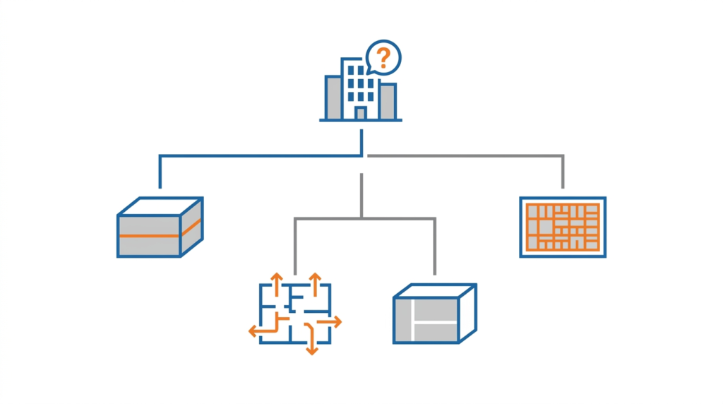
A. Types of Egress Models
| Type | How It Works | Examples |
|---|---|---|
| Hydraulic or network (flow) models | Treat occupants as a fluid flowing through a network of exits; often hand-calculable | SFPE hydraulic method, EVACNET4 |
| Agent-based or continuous models | Each occupant is an individual with its own attributes and movement behavior | Pathfinder (steering mode), MassMotion, Simulex |
| Grid or cellular models | Space is divided into cells; occupants move cell to cell | STEPS, buildingEXODUS |
The categories overlap, and individual products often offer more than one mode.
B. Pathfinder
Pathfinder is a commercial egress model developed by Thunderhead Engineering. It has two main movement modes:
| Mode | Description |
|---|---|
| Steering mode | Simulates individual occupants with steering behavior, collision avoidance, and individual attributes |
| SFPE mode | Uses the SFPE hydraulic approach, with flow limited at doors and stairs in a manner similar to hand calculations |
Pathfinder can use fire data (such as visibility and FED) from FDS or PyroSim results, so that occupant movement can be affected by smoke conditions.
C. STEPS
STEPS (Simulation of Transient Evacuation and Pedestrian movementS) is a commercial egress and pedestrian movement model developed by Mott MacDonald. It is an agent-based, grid-based model and is used extensively for transportation facilities, stadiums, and large public buildings.
D. Other Egress Models
Other widely used models include buildingEXODUS (University of Greenwich), MassMotion (Oasys), Simulex (IES), and FDS+Evac. ISO/TR 16738 provides technical information on methods for evaluating behavior and movement of people.
E. The Capabilities
Most egress models predict:
- Evacuation time
- Exit usage and exit selection
- Bottlenecks and queuing
- Occupant density
- Flow rates
F. The Inputs
| Input | Description |
|---|---|
| Occupant load | Number and distribution of occupants |
| Occupant characteristics | Age, mobility, familiarity, alertness |
| Pre-movement time | Delay before purposeful movement begins, often specified as a distribution |
| Walking speed | Speed on level surfaces and stairs, often a distribution |
| Exit selection | How occupants choose exits (nearest, familiar, or assigned) |
| Geometry | Doors, stairs, corridors, and widths |
| Exit availability | Whether any exit is blocked, as in worst-case scenarios |
G. The Pre-Movement Time Challenge
The pre-movement time is often the largest and most uncertain component of RSET. It depends on the type of alarm (voice versus bells), occupant alertness, familiarity with the building, the presence of staff or trained wardens, and the occupancy type. Sleeping occupants, for example, respond differently from awake occupants.
The pre-movement time is not determined by the model; it is an input. The engineer must select it based on the occupancy, the alarm system, and available data from the literature and from guidance documents.
H. Occupants with Disabilities
Occupants with mobility, visual, hearing, or cognitive impairments may move more slowly, need assistance, or use different routes (such as areas of refuge or evacuation elevators). Egress models should represent these occupants explicitly, not by a single average walking speed.
I. Limits of Egress Models
Egress models simulate movement well but represent human behavior only through the inputs. Most models do not capture complex behaviors such as seeking out family members, investigating the fire, or fighting the fire. These behaviors must be reflected in the pre-movement time and in the scenario design.
Key point: Egress models predict evacuation time. Pre-movement time is often the largest and most uncertain component of RSET.
Key Article: Article 123 — Exit Access, Exit, and Exit Discharge Explained
Pro Tip: Use conservative pre-movement times and run sensitivity cases. The actual time may be longer than the model predicts.
◆ Section 8: Verification, Validation, and Quality Assurance
Model validation is the process of demonstrating that a model produces accurate results for the conditions being analyzed.
A. The Standards and Guidance
| Standard | Scope |
|---|---|
| ASTM E1355 | Evaluating the predictive capability of deterministic fire models |
| ASTM E1472 | Documenting computer software for fire models |
| ASTM E1591 | Obtaining data for deterministic numerical fire models |
| ISO 16730 | Assessment, verification, and validation of calculation methods |
| ISO/TR 16738 | Methods for evaluating behavior and movement of people |
| IMO MSC.1/Circ.1533 | Evacuation analysis guidelines for ships, with test cases often used to check egress software |
B. Verification Versus Validation
| Step | Question Answered |
|---|---|
| Verification | Does the software solve the equations correctly? |
| Validation | Do the equations represent the real physics, as shown by comparison to experiments? |
| Uncertainty analysis | How uncertain are the results? |
| Sensitivity analysis | Which inputs most affect the results? |
| Documentation | Is the work recorded so a reviewer can reproduce it? |
Software developers are generally responsible for verification and for validation of the general model. The engineer is responsible for showing that the model is appropriate for the specific application.
C. The Validation Data
Validation data comes from full-scale fire tests, reduced-scale tests, real fire incidents, and benchmark experiments. For egress models, data also comes from evacuation drills, controlled movement experiments, and published flow-rate and speed data.
D. Application-Specific Validation
The validation must be specific to the application:
- A model validated for a residential room is not necessarily valid for an atrium
- A model validated for a slow fire is not necessarily valid for a fast fire
- A model validated for a sprinklered space is not necessarily valid for an unsprinklered space
E. Configuration Management
Software changes between versions. The report should state the exact software name, version, and input files used, and the project should keep the input files so the analysis can be repeated.
Key point: Model validation is essential for reliable results, and it must be specific to the application.
Pro Tip: Use the model’s standard validation cases as a starting point, but demonstrate applicability for the specific scenario.
◆ Section 9: Model Selection
The model selection determines the quality of the analysis. The wrong model produces misleading results.
A. The Selection Criteria
| Criterion | Consideration |
|---|---|
| Geometry | Complexity, size, aspect ratio |
| Flow | One-, two-, or three-dimensional |
| Fire | Size, growth rate, location |
| Required accuracy | Level of detail needed |
| Available data | Input data quality |
| Analyst expertise | Training and experience |
| Computational resources | Available computing power |
| Time and cost | Analysis timeline and software cost |
| AHJ acceptance | Whether the AHJ is familiar with and accepts the model |
B. The Decision Matrix
| Problem | Model |
|---|---|
| Simple room, fast screening | Hand calculations |
| Simple geometry, multi-compartment | CFAST |
| Complex geometry, 3D flow | FDS |
| Smoke control system | CONTAM, CFAST, FDS (per NFPA 92) |
| Evacuation analysis | Pathfinder, STEPS, buildingEXODUS, or hydraulic methods |
| Coupled fire and egress | FDS with Pathfinder, or FDS+Evac |
C. The Simplest Model Principle
Use the simplest model that adequately addresses the problem. A complex model with uncertain inputs may be less reliable than a simple model with well-characterized inputs.
D. Progressive Modeling
A common approach is to begin with hand calculations, move to a zone model for scenario screening, and use CFD only for the scenarios and spaces that justify it.
Key point: Use the simplest model that adequately addresses the problem.
Pro Tip: Do not use a complex model for a simple problem. The complexity may not be justified, and the results may be less reliable.
◆ Section 10: Practical Considerations
Using fire and egress models in practice requires attention to input data, scenarios, assumptions, sensitivity, documentation, and review.
A. The Input Data
| Data | Source |
|---|---|
| Heat release rate | SFPE Handbook, NIST data, manufacturer data, test data |
| Fire growth rate | SFPE Handbook, NFPA 72 and NFPA 92 annexes |
| Soot and CO yields | Literature and test data |
| Material properties | Manufacturer data, test data |
| Geometry | Architectural drawings, BIM |
| Occupant characteristics | Building data, occupancy data |
| Pre-movement time | Literature, test data, and guidance documents |
B. Design Fire Scenarios
The selection of design fire scenarios is a major driver of results. Scenarios should be agreed with the AHJ and should cover the credible worst-case conditions for the building, including fires in the most hazardous location, fires that block a primary exit, and fires with a system failure or impairment (such as a sprinkler or smoke control failure) where required by the design brief.
C. The Assumptions
| Assumption | Consideration |
|---|---|
| Ventilation | Open or closed? |
| Sprinkler activation | Will the sprinkler activate, and when? |
| Door position | Open or closed? |
| HVAC operation | Operating or off? |
| Occupant behavior | Prompt response or delayed? |
D. The Sensitivity Analysis
A sensitivity analysis identifies the inputs that most affect the results. The engineer should focus on the sensitive inputs and verify their values.
E. Computing Resources
CFD models may need multi-core processors, substantial memory, and long run times. Plan the schedule and the hardware early, and consider cloud computing for large models.
F. The Peer Review
Peer review is essential for modeling. The reviewer should be independent and qualified.
G. The Report
The report should include the objectives, scenarios, model description, software versions, inputs and assumptions, mesh or geometry description, results, sensitivity analysis, limitations, and conclusions. A reviewer should be able to reproduce the analysis from the report.
Key point: Using fire and egress models requires attention to input data, scenarios, assumptions, sensitivity, and peer review.
Pro Tip: Document all inputs and assumptions. The documentation is the evidence that the analysis is defensible.
◆ Section 11: Design Checklist
| Item | Status | Notes |
|---|---|---|
| Problem defined | ☐ | What is being analyzed |
| Performance objectives and tenability criteria agreed with AHJ | ☐ | Design brief |
| Design fire scenarios agreed | ☐ | Location, growth rate, failures |
| Model selected | ☐ | Based on selection criteria |
| Analyst qualified | ☐ | Training and experience |
| Input data collected | ☐ | HRR, geometry, occupancy |
| Assumptions documented | ☐ | Ventilation, doors, HVAC |
| Model validated for the application | ☐ | Documented |
| Mesh or grid sensitivity done (CFD) | ☐ | Show results are grid-independent |
| Sensitivity analysis performed | ☐ | Identify key inputs |
| Hand calculation check | ☐ | Reasonableness check |
| ASET/RSET analysis | ☐ | Comparison with agreed margin |
| Results interpreted | ☐ | By qualified engineer |
| Peer review performed | ☐ | Independent |
| Results documented | ☐ | Report with all inputs and software versions |
| AHJ reviewed and approved | ☐ | Required |
◆ Section 12: Common Mistakes and How to Avoid Them
| Mistake | Why It’s a Problem | How to Fix |
|---|---|---|
| Using a complex model for a simple problem | Unjustified complexity and cost | Use the simplest adequate model |
| Using a simple model for a complex problem | Inadequate analysis | Use an appropriate model |
| Not validating the model for the application | Results may be wrong | Document applicability |
| Not performing a mesh sensitivity study | Results may be grid artifacts | Refine the grid and compare |
| Not documenting inputs and software versions | Results cannot be defended or repeated | Document everything |
| Not performing sensitivity analysis | Key inputs not verified | Vary key inputs |
| Agreeing on tenability criteria late | Rework and AHJ disputes | Agree on the design brief first |
| Using optimistic pre-movement times | RSET underestimated | Use conservative, documented values |
| Treating results as answers | Numbers without meaning | Interpret with a qualified engineer |
| Skipping peer review | Errors not caught | Require independent review |
| Not engaging the AHJ | Surprises at review | Hold a pre-submittal meeting |
| Using an unqualified analyst | Errors and misinterpretation | Require training and experience |
| Ignoring limitations | False confidence | State limitations in the report |
Key point: Most modeling problems are selection, input data, and interpretation problems, not software problems.
◆ Section 13: Conclusion
Fire and egress models are the analytical tools of performance-based fire engineering. They allow the engineer to predict fire behavior and occupant response, compare ASET to RSET, and demonstrate that the design achieves the performance objectives.
The two model families are:
- Fire models: hand calculations, CFAST (zone), FDS (CFD), and specialized models
- Egress models: hydraulic methods, Pathfinder, STEPS, buildingEXODUS, and other models
The critical elements are:
- Agreed criteria: performance objectives, tenability criteria, and scenarios settled with the AHJ
- Model selection: the right model for the problem
- Input data: accurate and documented
- Validation: for the specific application
- Sensitivity analysis: identifies key inputs
- Interpretation: by a qualified engineer
- Peer review: independent assurance
- Documentation: the evidence of the analysis
The most common failure is treating models as answers rather than tools. They are tools that support engineering judgment, and their results must be interpreted by qualified professionals.
Key Takeaways:
- Fire and egress models are the analytical tools of performance-based fire engineering.
- ASET versus RSET, with an agreed margin and agreed tenability criteria, is the central comparison.
- Start with hand calculations; use the simplest model that adequately addresses the problem.
- FDS is the most capable CFD fire model; CFAST is a faster zone model for simpler geometries.
- Pathfinder, STEPS, and buildingEXODUS are widely used egress models.
- Pre-movement time is often the largest and most uncertain component of RSET.
- Validation must be specific to the application, and CFD results need a mesh sensitivity study.
- Document all inputs, assumptions, and software versions.
- Peer review is essential for assurance.
- The most common failure is treating models as answers rather than tools.
Take Action Today:
- Define the problem to be analyzed.
- Agree on objectives, tenability criteria, and design fire scenarios with the AHJ.
- Select the model based on the selection criteria, starting with hand calculations.
- Verify the analyst’s qualifications.
- Collect the input data and document all assumptions.
- Validate the model for the specific application and, for CFD, perform a mesh sensitivity study.
- Perform a sensitivity analysis.
- Perform the ASET/RSET analysis with the agreed margin.
- Interpret the results with a qualified engineer.
- Require a peer review.
- Document the results in a report with software versions and input files.
- Submit to the AHJ for review and approval.
Continue Reading from Our Series:
- Related guide: Article 162 — Performance-Based Design and Fire Engineering (NFPA 101 Ch. 5)
- Related guide: Article 161 — NFPA 101 vs. IBC: Key Differences Explained
- Related guide: Article 158 — Digital Twins for Fire Safety Management
- Read more: Article 164 — Equivalency and Alternate Methods of Compliance (planned)
About This Guide: This article is part of a series on commercial building fire safety, written for facility managers, architects, and code officials. It references model codes and standards for educational purposes. Always consult your local AHJ and a qualified fire protection engineer for project-specific requirements.