IMPORTANT DISCLAIMER: This guide references NFPA 96, Standard for Ventilation Control and Fire Protection of Commercial Cooking Operations (2024 edition); the International Mechanical Code (IMC), Chapter 5 (Exhaust Systems); the Uniform Mechanical Code (UMC), Chapter 5 (Exhaust Systems); UL 1978, Grease Ducts; and UL 2221, Tests of Fire Resistive Grease Duct Enclosure Assemblies. These codes and standards vary by edition and are frequently amended by state and local jurisdictions. NFPA 96 was reorganized in the 2024 edition, and section and table numbers (including the grease buildup inspection table, previously Table 11.4 and now Table 12.4) may differ from earlier editions. Verify section numbers against your AHJ-adopted edition. Local amendments and the edition adopted by your Authority Having Jurisdiction (AHJ) always control. This guide is a starting point only. Always verify the specific requirements applicable to your project with your local AHJ.
Grease ducts are the hidden fire path in commercial kitchens. Grease-laden vapors rise from cooking equipment, enter the exhaust hood, and condense on the interior surfaces of the duct system. Over time, that condensation builds into a combustible lining that can ignite and propagate fire through the building, often into concealed spaces where suppression systems cannot reach.
NFPA 96 governs the design, installation, and maintenance of these systems. The standard addresses duct construction, clearance to combustibles, access for cleaning and inspection, fire suppression, and the cleaning schedules that determine when grease must be removed. A grease duct that meets the code at installation can become a fire hazard within months if the cleaning schedule is neglected.
This article covers the requirements for grease duct design and fire safety under NFPA 96, with a focus on the details that determine whether the system performs when a fire starts inside the duct.
◆ Section 1: Why Grease Ducts Are Different
Grease ducts are not ordinary exhaust ducts. They carry a fuel load (grease) that accumulates on the duct walls and can ignite from a cooking flare-up or a spark.
| Factor | Challenge |
|---|---|
| Combustible lining | Grease condenses on duct walls and forms a flammable layer |
| Concealed routing | Ducts often pass through concealed spaces, shafts, and floors |
| Fire propagation path | A duct fire can spread vertically and horizontally through the building |
| Limited access | Access panels are required, but they are often obstructed or omitted |
| Cleaning dependence | The system relies on scheduled cleaning to remain safe |
| Suppression interface | The duct may or may not be protected by the hood suppression system |
Key point: A grease duct is a fuel-lined chimney. The code requirements for construction, clearance, and access exist because the duct itself will burn if grease is allowed to accumulate.
Key Article: Article 107 — Fire Safety for Restaurants and Commercial Kitchens
Pro Tip: The most common grease duct fire is not a failure of the duct material. It is a failure of the cleaning schedule.
◆ Section 2: Regulatory Framework
Grease duct design is governed by NFPA 96 and adopted by the mechanical code.
| Standard | Scope | Key Provisions |
|---|---|---|
| NFPA 96 | Ventilation control and fire protection for commercial cooking | Duct construction, clearance, access, suppression, cleaning schedules |
| IMC Chapter 5 | Exhaust systems | Adopts or parallels NFPA 96 for grease ducts; velocity, cleanout, and termination provisions |
| UMC Chapter 5 | Exhaust systems | Extracts NFPA 96 provisions for grease ducts |
| UL 1978 | Grease ducts | Listing standard for factory-built grease ducts |
| UL 2221 | Factory-built grease duct enclosure assemblies | Fire test and listing of factory-built enclosures |
| ASTM E2336 | Fire-resistive grease duct enclosure systems | Test method for field-applied enclosure materials |
| UL 300 / NFPA 17A | Wet chemical extinguishing systems | Listing and installation of hood and duct suppression |
Key point: NFPA 96 is the primary standard. The IMC and UMC adopt or extract it, so compliance with NFPA 96 is a code requirement in most jurisdictions.
Key Article: Article 115 — Kitchen Hood Suppression Systems (NFPA 96)
Pro Tip: Verify which edition of NFPA 96 your AHJ has adopted. The 2024 edition renumbered several sections and changed the inspection table reference.
◆ Section 3: Duct Materials, Joints, and Dedicated Systems
Before looking at enclosures, the duct itself must be built to contain a fire and grease.
A. Materials and Thickness
Ducts of welded construction must be made of:
| Material | Minimum Thickness |
|---|---|
| Carbon steel | 0.054 in. (No. 16 MSG) |
| Stainless steel | 0.043 in. (No. 18 MSG) |
Listed factory-built grease ducts are built and installed per their listing (UL 1978) instead.
B. Joints and Seams
Field-fabricated ducts must have continuous liquid-tight external welds on all seams, joints, penetrations, and duct-to-hood collar connections. Mechanical joints are permitted only where the duct is listed for them. Liquid tightness matters because a leak lets grease escape into concealed spaces and lets fire escape the duct. Some jurisdictions also require a pressure or leak test before the duct is concealed.
C. Dedicated System
The grease duct system must serve only the cooking exhaust, and it must not be combined with other exhaust systems. Do not connect it to general exhaust, toilet exhaust, or dishwasher exhaust. Solid-fuel cooking requires its own separate system.
D. No Fire Dampers
Fire dampers must not be installed in grease ducts. A damper would trap grease and could close and interrupt exhaust during a fire. This is why rated shaft or listed enclosure construction is required where the duct passes through fire-rated assemblies.
E. Exhaust Velocity
The design velocity in the grease duct must be not less than 500 fpm (IMC 506.3.4 and NFPA 96). The IMC allows short transitions (not more than 3 ft long) that connect mismatched hood or fan openings and do not trap grease. This keeps grease entrained and moving toward the fan and away from the duct walls. Verify the velocity requirement in your adopted edition.
Pro Tip: A duct with an inserted damper or a shared branch is a plan review rejection and a field fire hazard.
◆ Section 4: Duct Enclosure and Protection
Where a grease duct passes through combustible construction or through fire-rated floors and walls, it must be enclosed or protected in one of several ways.
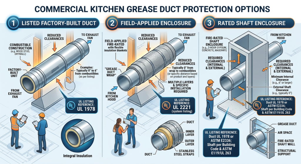
A. Listed Factory-Built Grease Ducts
Listed factory-built grease ducts (UL 1978) must be installed in accordance with their listing and the manufacturer’s instructions. The listing specifies construction, required clearance to combustibles, and any enclosure requirements.
B. Field-Applied Grease Duct Enclosures
Where a field-applied enclosure is used, the duct must be continuously covered on all sides from the point at which the duct penetrates a ceiling, wall, or floor to the outlet terminal. The enclosure material must be listed in accordance with ASTM E2336 and installed per the manufacturer’s instructions.
The enclosure must be protected with a through-penetration firestop system classified in accordance with ASTM E814 or UL 1479, with an “F” and “T” rating equal to the fire resistance rating of the assembly being penetrated.
C. Factory-Built Grease Duct Enclosures
Factory-built enclosures must be listed in accordance with UL 2221. The protection system must be installed in accordance with the manufacturer’s instructions and the listing requirements.
D. Rated Shaft Enclosure
In buildings more than one story in height, and in buildings where the roof-ceiling assembly is fire-resistance rated, the duct must be enclosed in a continuous enclosure (a rated shaft or a listed enclosure system). NFPA 96 §7.7.2.1 sets the minimum rating:
| Building Height | Minimum Enclosure Fire-Resistance Rating |
|---|---|
| Fewer than four stories | 1 hour |
| Four stories or more | 2 hours |
The enclosure must also meet the rating of the assemblies it passes through, and it must be sealed around the duct at the point where it penetrates the first fire-rated barrier after the hood. Verify against your adopted edition and the IBC/IMC.
E. Clearance to Combustibles
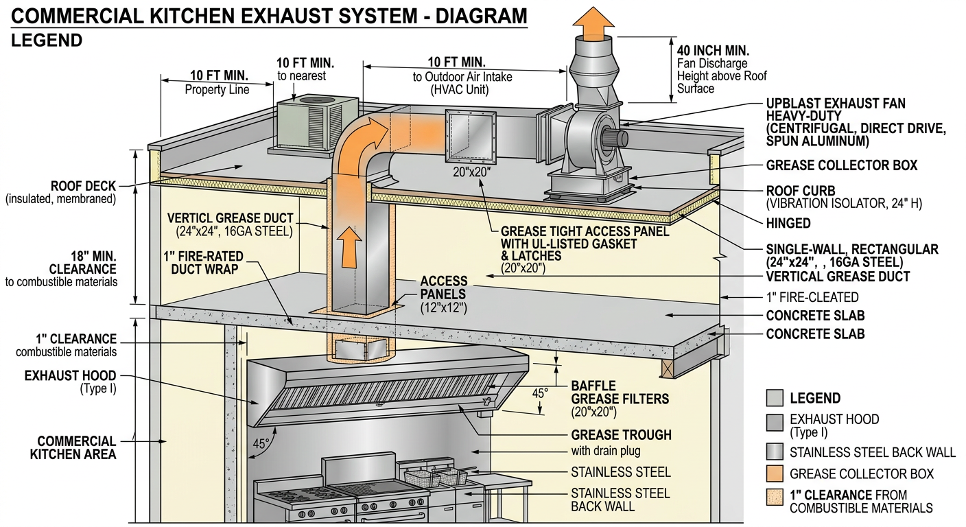
Where an enclosure is not required, hoods, grease removal devices, exhaust fans, and ducts must have these minimum clearances (NFPA 96 §4.2.1):
| Adjacent Material | Minimum Clearance |
|---|---|
| Combustible material | 18 in. |
| Limited-combustible material | 3 in. |
| Noncombustible material | 0 in. |
Where the duct is inside an enclosure, the clearance is measured from the duct to the interior surface of the enclosure:
| Enclosure Construction | Minimum Clearance |
|---|---|
| Combustible | 18 in. |
| Noncombustible or limited-combustible | 6 in. |
Reduced clearances are permitted only with approved protection methods applied to the adjacent construction (not to the duct), or where the duct or enclosure is listed for smaller clearances.
The listing for a grease duct enclosure must identify the clearance options for which it has been evaluated:
| Clearance Option | Description |
|---|---|
| Open combustible construction | Clearance at manufacturer’s requested dimensions |
| Closed combustible construction | Clearance at manufacturer’s requested dimensions, with or without specified ventilation |
| Rated shaft clearance | Clearance at manufacturer’s requested dimensions, with or without specified ventilation |
Key point: The clearance is not a universal number. It is the dimension specified in the code or listing for the specific construction condition. Using a clearance from one condition in a different condition voids the listing.
Pro Tip: The duct is permitted to contact noncombustible floors, interior walls, and other noncombustible structures, but it must not be in contact for more than 50 percent of its surface area for each linear foot of contact length.
◆ Section 5: Duct Slope and Drainage
Grease must be able to drain from the duct. NFPA 96 §7.1.3 requires horizontal ducts to be installed with a minimum slope toward the hood or an approved drain or reservoir:
| Horizontal Run | Minimum Slope |
|---|---|
| Up to 75 feet | 2 percent (1/4 inch per linear foot) |
| Greater than 75 feet | 8.3 percent (1 inch per linear foot) |
Factory-built grease ducts are permitted to be installed at a lesser slope in accordance with their listing and the manufacturer’s instructions.
Drains must be provided at low points in horizontal ducts. Where provided, drains must be continuously welded to the exhaust duct or installed in accordance with the listing.
Key point: Ducts must be installed without forming dips or traps. In manifold systems, the lowest end of the main duct must be connected flush on the bottom with the branch duct.
Pro Tip: Grease that cannot drain will accumulate and become a fire load. Slope and drainage are not optional. They are part of the fire safety strategy.
◆ Section 6: Access Panels and Inspection
Access panels are required so that the duct can be inspected and cleaned.
A. Where Openings Are Required
Openings must be provided at the sides or top of the duct, whichever is more accessible, and at changes of direction. Openings are not required in portions of the duct that are accessible from the duct entry or discharge.
B. Horizontal Ducts
NFPA 96 §7.4.1 requires:
- At least one 20 in. × 20 in. opening for personnel entry on horizontal ducts.
- Where a 20 × 20 in. opening is not possible, openings large enough to permit thorough cleaning at 12 ft intervals.
- Safe access and a work platform where openings are not easily reachable from a 10 ft stepladder.
The IMC adds cleanout rules for sections not accessible from the duct entry or discharge: cleanouts not more than 20 ft apart and not more than 10 ft from changes of direction greater than 45 degrees (IMC 506.3.8). Where both codes apply, the more stringent requirement governs.
C. Vertical Ducts
Where personnel entry is possible, access must be provided at the top of the vertical riser to accommodate descent. Where personnel entry is not possible, adequate access for cleaning must be provided on each floor.
D. Panel Construction and Signage
The 20 × 20 in. figure is the personnel-entry opening size, not a universal panel size. Smaller panels are sized to permit thorough cleaning. Panels must be constructed of the same material and thickness as the duct and use liquid-tight gasketing rated for 1,500°F.
Each access panel must have a sign stating “ACCESS PANEL – DO NOT OBSTRUCT.”
E. Access for Fans
Exhaust fans with ductwork connected to both sides must have access for cleaning and inspection within 3 feet of each side of the fan. Wall-mounted exhaust fans must have access within 3 feet of the fan.
F. Access Through Enclosures
Where the duct is enclosed in a shaft or by a listed enclosure, access to each opening must be maintained, and any access penetration must be protected so the enclosure rating is preserved. The enclosure listing governs how to do this.
Key point: Access panels are not a convenience. They are a code requirement. A duct that cannot be inspected cannot be verified as clean.
Pro Tip: Access panels are frequently obstructed by stored materials, insulation, or building finishes. The “DO NOT OBSTRUCT” sign exists because this is a common failure.
◆ Section 7: Cleaning Schedules and Grease Depth Limits
The cleaning schedule is based on the volume and type of cooking.
A. Inspection Frequency (NFPA 96 Table 12.4; Table 11.4 in earlier editions)
| Type of Cooking | Inspection Frequency |
|---|---|
| Solid fuel cooking | Monthly |
| High-volume (24-hour, charbroiling, wok) | Quarterly |
| Moderate-volume | Semiannually |
| Low-volume (churches, seasonal, senior centers) | Annually |
B. Grease Depth Triggers
Cleaning is triggered when inspection finds grease deposits at specific depths:
| Location | Trigger Depth |
|---|---|
| Most surfaces | 0.078 inch (2000 μm) |
| Fan housings | 0.125 inch (3175 μm) |
A grease depth gauge comb is placed on the surface to measure the depth. Verify the trigger values against your adopted edition.
C. Cleaning Requirements
Where the exhaust system is found to be contaminated, the contaminated portions must be cleaned by a properly trained, qualified, and certified person acceptable to the AHJ. Electrical switches that could be activated accidentally must be locked out at the start of cleaning. Cleaning must cover the full system: hood, filters, plenum, duct, and fan.
D. Reporting and Records
After cleaning, the contractor must:
- Place a dated sticker or tag on the hood or at the access point showing the date cleaned and the contractor.
- Report areas that could not be accessed or cleaned (for example, a missing access panel).
- Provide a written report or certificate of performance to the owner.
The owner must keep inspection and cleaning records on premises for AHJ and insurer review.
Key point: The inspection schedule is based on cooking volume, not restaurant size. A small restaurant doing 24-hour wok cooking is inspected quarterly.
Pro Tip: The grease depth triggers (0.078 inch / 0.125 inch) are the objective standard. “It looks clean” is not a compliance determination.
◆ Section 8: Fire Suppression Integration
The relationship between the hood suppression system and the grease duct determines whether the duct is protected.
A. If the Suppression System Protects the Duct
NFPA 96 requires extinguishing protection for the appliances, hood, grease removal devices, plenum, and exhaust duct. Most restaurants meet this with a UL 300 listed wet chemical system installed per NFPA 17A. The system must be listed for the duct length and size, with duct nozzles and detection placed per its listing. The duct is then considered protected.
B. If the Suppression System Does Not Protect the Duct
If the chemical system is not designed to fully protect the duct (for example, a very long or large duct), the duct will also require fire sprinklers installed per NFPA 13.
C. System Activation Interfaces
On activation, the system must:
- Shut off fuel and electric power to appliances under the hood (via mechanical or electrical interlock).
- Leave the exhaust fan running (or start it, if it was off), because the fan helps contain fire and smoke in the duct.
- Alert occupants through the building fire alarm system where one exists.
A manual pull station must be installed in an accessible location along the egress path. Class K portable extinguishers are also required near the cooking appliances.
Key Point: The duct protection is not automatic. The designer must confirm whether the suppression system covers the duct and, if not, provide sprinkler protection.
Pro Tip: This is a common plan review issue. The suppression system submittal must clearly state whether the duct is protected or whether sprinklers are required.
◆ Section 9: Rooftop and Wall Terminations
The termination of the grease duct is a critical detail.
A. Rooftop Terminations
Rooftop terminations must have:
| Requirement | Dimension |
|---|---|
| Horizontal clearance to adjacent buildings, property lines, air intakes | 10 feet minimum |
| Horizontal clearance to combustible structure | 5 feet minimum (verify in adopted edition) |
| Vertical separation above air intakes within 10 feet | 3 feet minimum |
The fan must be a hinged upblast fan with flexible weatherproof electrical cable and a service hold-open retainer to permit inspection and cleaning. Where the fan attaches to the ductwork, the ductwork must be at least 18 inches away from any roof surface, and the fan must discharge at least 40 inches away from any roof surface.
A grease containment system (such as a collection tray or approved grease-absorbing device) is required where grease could drip onto the roof. This protects roofing materials from grease saturation and ignition.
B. Wall Terminations
Wall terminations must be through a noncombustible wall with at least 10 feet of clearance from the outlet to adjacent buildings, property lines, grade level, combustible construction, electrical equipment, and air intakes.
Key Point: The termination clearances prevent grease-laden exhaust from igniting adjacent structures or being drawn into air intakes.
◆ Section 10: Testing and Acceptance
Before the system is accepted and the ductwork is concealed:
- Verify that all welds and joints are liquid-tight. The AHJ may require a leak, light, or pressure test.
- Confirm that access panels, slope, drains, and clearances match the approved drawings.
- Verify the enclosure installation against the listing, including firestop at each penetration.
- Test the suppression system and its fuel and power shutdown, and verify exhaust fan operation.
Pro Tip: Do not allow the duct to be concealed until the AHJ or third-party inspector has signed off. Fixing a leaking weld after the shaft is built is expensive.
◆ Section 11: After a Duct Fire
A duct fire can damage the duct, the enclosure, and the structure without being obvious from the kitchen.
- Do not restart the cooking operation until the duct and enclosure have been inspected for warping, burn-through, and failed joints.
- Inspect firestop and adjacent combustibles for heat damage.
- Replace damaged duct sections and enclosure materials per the listing.
- Have the entire system professionally cleaned and re-certified.
- Notify the AHJ and insurer as required.
◆ Section 12: Design Checklist for Grease Duct Fire Safety
| Item | Status | Notes |
|---|---|---|
| Duct material and gauge | ☐ | 16 MSG carbon steel or 18 MSG stainless, or listed (UL 1978) |
| Joints liquid-tight | ☐ | Continuous external welds or listed joints |
| Dedicated system | ☐ | No shared exhaust; solid fuel separate |
| No fire dampers | ☐ | None in grease duct |
| Exhaust velocity | ☐ | Not less than 500 fpm |
| Duct type determined | ☐ | Listed factory-built, field-applied enclosure, or shaft |
| Listing verified | ☐ | UL 1978 for factory-built duct; UL 2221 / ASTM E2336 for enclosures |
| Shaft rating | ☐ | 1 hr under four stories; 2 hr for four stories or more |
| Clearance confirmed | ☐ | 18 in. combustible / 3 in. limited-combustible / 0 in. noncombustible; 18 in. / 6 in. inside enclosures; or per listing |
| Through-penetration firestop | ☐ | F and T rating equal to assembly rating |
| Duct slope | ☐ | 2% up to 75 ft; 8.3% (1 in./ft) over 75 ft |
| Drains provided | ☐ | At low points |
| Personnel-entry opening | ☐ | One 20×20 in. on horizontal ducts, or openings every 12 ft |
| IMC cleanout spacing | ☐ | 20 ft max apart; 10 ft max from changes of direction (where IMC applies) |
| Access panel construction and signage | ☐ | 1,500°F gaskets; “ACCESS PANEL – DO NOT OBSTRUCT” |
| Fan access | ☐ | Within 3 ft of each side |
| Inspection frequency determined | ☐ | Per cooking volume (monthly to annual) |
| Grease depth triggers established | ☐ | 0.078 in. (most); 0.125 in. (fan housing) |
| Duct suppression coverage confirmed | ☐ | By UL 300 hood system or by sprinklers per NFPA 13 |
| Suppression interlocks tested | ☐ | Fuel/power shutdown; fan operation |
| Rooftop termination clearances | ☐ | 10 ft to buildings; 5 ft to combustible structure |
| Upblast fan requirements | ☐ | Hinged; 18 in. duct clearance; 40 in. discharge |
| Grease containment at roof | ☐ | Where grease could reach roofing |
| Acceptance testing completed | ☐ | Before duct is concealed |
| Cleaning records and certificates | ☐ | On premises |
◆ Section 13: Common Mistakes and How to Avoid Them
| Mistake | Why It’s a Problem | How to Fix |
|---|---|---|
| Skipping the cleaning schedule | Grease accumulates; fire risk increases | Follow volume-based inspection schedule |
| Assuming “it looks clean” is sufficient | Subjective judgment; no objective standard | Use grease depth gauge comb; measure |
| Obstructing access panels | Duct cannot be inspected or cleaned | Post “DO NOT OBSTRUCT” signs; enforce |
| Using wrong clearance | Listing voided; fire exposure risk | Verify clearance for the specific condition (open vs. enclosed) |
| No slope on horizontal duct | Grease accumulates; cannot drain | Install at required slope; provide drains |
| Assuming hood suppression protects duct | Duct may not be covered | Confirm coverage; provide sprinklers if not |
| No firestop at duct penetration | Rating lost at floor/wall | Install listed through-penetration firestop |
| Installing a fire damper in the duct | Traps grease; can stop exhaust in a fire | Use rated shaft or listed enclosure instead |
| Tying other exhaust into the grease duct | Spreads fire; defeats dedicated design | Keep the grease duct a dedicated system |
| Leaky field welds | Grease and fire escape into concealed spaces | Weld continuously; test before concealing |
| Fan not hinged/accessible | Cannot inspect or clean | Specify hinged upblast fan |
| Rooftop termination too close to building | Grease exhaust can ignite adjacent structure | Verify 10-ft clearance |
| Restarting after a duct fire without inspection | Hidden damage; repeat fire | Inspect, repair, and clean before reopening |
◆ Section 14: Conclusion
Grease ducts are the hidden fire path in commercial kitchens. The grease that condenses on duct walls is a fuel load that can ignite and propagate fire through the building.
NFPA 96 establishes the requirements: liquid-tight duct construction, a dedicated system with no dampers, enclosure and clearance per code or listing, slope and drainage, access panels for inspection, and cleaning schedules based on cooking volume. The suppression system must be confirmed to cover the duct, or sprinklers must be provided. The termination clearances prevent external fire spread.
A grease duct that meets the code at installation can become a fire hazard within months if the cleaning schedule is neglected. The system is only as safe as its maintenance.
Key Takeaways
- Grease ducts are fuel-lined chimneys; the grease that condenses on duct walls is the fire load.
- Ducts must be liquid-tight, dedicated to cooking exhaust, designed for at least 500 fpm, and free of fire dampers.
- Factory-built ducts are listed to UL 1978 and installed per listing; enclosures are listed to UL 2221 (factory-built) or ASTM E2336 (field-applied).
- Clearance is not a universal number: 18 in. to combustibles, 3 in. to limited-combustibles, and 0 in. to noncombustibles where no enclosure is required; 18 in. or 6 in. inside an enclosure, depending on its construction; or as listed.
- Multistory ducts require a continuous enclosure rated 1 hour (under four stories) or 2 hours (four stories or more).
- Horizontal ducts require slope (2% up to 75 ft; 8.3% over 75 ft) and drains at low points.
- Horizontal ducts need at least one 20×20 in. personnel-entry opening, or cleaning openings every 12 ft where entry is not possible; the IMC adds 20 ft / 10 ft cleanout spacing.
- Inspection frequency is based on cooking volume: monthly (solid fuel), quarterly (high-volume), semiannual (moderate), annual (low-volume).
- Grease depth triggers: 0.078 inch on most surfaces; 0.125 inch in fan housings.
- If the hood suppression system does not protect the duct, sprinklers are required per NFPA 13.
- Rooftop terminations require 10-ft clearance to buildings, with 3 ft above air intakes.
- After a duct fire, inspect and repair before restarting cooking operations.
Take Action Today
- Verify the grease duct material, joints, and listing for each construction condition.
- Confirm there are no fire dampers and no shared exhaust connections.
- Confirm horizontal duct slope and drainage.
- Verify access openings are present, correctly sized, and unobstructed.
- Establish the inspection schedule based on cooking volume.
- Train staff on the grease depth gauge and cleaning triggers.
- Confirm whether the hood suppression system covers the duct or whether sprinklers are required.
- Verify rooftop termination clearances and fan requirements.
- Maintain cleaning records and certificates on premises.
Continue Reading from Our Series:
-
Related guide: Fire Safety for Restaurants and Commercial Kitchens (Article 107)
-
Learn more: Kitchen Hood Suppression Systems (NFPA 96) (Article 115)
-
Read more: Fire Damper and Smoke Damper Requirements (Article 136)