IMPORTANT DISCLAIMER: This guide references the International Building Code (IBC), Section 717 (Ducts and Air Transfer Openings); the International Mechanical Code (IMC), Section 607; UL 555, Standard for Fire Dampers; UL 555S, Standard for Smoke Dampers; UL 555C, Standard for Ceiling Dampers; NFPA 80, Standard for Fire Doors and Other Opening Protectives (2025 edition); NFPA 90A, Standard for the Installation of Air-Conditioning and Ventilating Systems; NFPA 72, National Fire Alarm and Signaling Code; and NFPA 105, Standard for Smoke Door Assemblies and Other Opening Protectives (2025 edition). These codes and standards vary by edition and are frequently amended by state and local jurisdictions. The 2025 editions of NFPA 80 and NFPA 105 revised their damper chapters, including new requirements for operability, prevention of blockage, and remote inspection methods. Chapter and section numbers also change between editions, so verify them against the edition your jurisdiction has adopted. The IBC damper provisions have been renumbered across editions (Section 717 in recent editions; Section 716 in earlier ones). Local amendments and the edition adopted by your Authority Having Jurisdiction (AHJ) always control. This guide is a starting point only. Always verify the requirements for your project with your local AHJ.
Fire dampers and smoke dampers are the critical link between HVAC systems and fire-rated assemblies. They protect duct penetrations through rated walls and floors, and they prevent smoke migration through ductwork. Unlike a wall or floor assembly, a damper has moving parts, and moving parts fail. A damper that is rusted, blocked, or improperly installed will not close when a fire starts, and the rated assembly it protects becomes a hole in the building’s passive fire protection.
The IBC establishes where dampers are required and which type is required at each location. UL 555 and UL 555S establish the ratings that determine whether a damper can perform its intended function. NFPA 80 and NFPA 105 establish how dampers are inspected, tested, and maintained after installation. NFPA 90A and NFPA 72 govern how dampers are tied into duct detection and the fire alarm system.
This article covers where dampers are required, the types of dampers and their ratings, installation, access, controls, smoke control applications, acceptance testing, and the ongoing testing that determines whether they work when needed.
◆ Section 1: Why Dampers Matter
A duct penetration through a rated wall or floor is a breach in the building’s passive fire protection. The damper is the component that restores the rating, if it works.
| Factor | Challenge |
|---|---|
| Moving parts | Dampers have blades, linkages, and actuators that can fail |
| Concealed location | Dampers are often above ceilings or in shafts, accessible only through access panels |
| Corrosion and debris | Rust, dust, and construction debris can bind damper components |
| Improper installation | A damper installed outside its listing will not perform as tested |
| Missing access | A damper that cannot be inspected cannot be verified as functional |
| Static vs. dynamic mismatch | A static damper in a dynamic system may not close against airflow |
| Control integration | A damper that is not tied to detection or the fire alarm system may never be told to close |
Key point: The damper is a mechanical device. It must be installed correctly, maintained properly, and tested periodically. A damper that is never inspected is a damper that is assumed to work.
Key Article: Article 134, Firestop Systems: Testing, Listings, and Inspection
Pro Tip: The most common damper failure is not a manufacturing defect. It is a damper that was never inspected because the access panel was obstructed or omitted.
◆ Section 2: Where Dampers Are Required
The IBC (Section 717.5 for vertical assemblies and 717.6 for horizontal assemblies) establishes where dampers are required. In general, dampers are required where ducts and air transfer openings penetrate:
| Assembly | Typical Damper Requirement |
|---|---|
| Fire walls | Fire damper |
| Fire barriers (including shaft enclosures and exit enclosures) | Fire damper |
| Fire partitions | Fire damper (subject to exceptions) |
| Smoke barriers | Smoke damper (or combination fire/smoke damper where the barrier is also fire-resistance rated) |
| Rated corridor walls | Corridor damper or fire damper, depending on the construction and sprinkler protection |
| Horizontal assemblies (floors, roof-ceiling assemblies) | Fire damper, ceiling radiation damper, or shaft enclosure, depending on the assembly |
Common exceptions. The IBC and IMC include exceptions that can eliminate the damper at some penetrations. Exact wording and conditions vary by edition. Typical examples include:
- Penetrations protected by a listed through-penetration firestop system or tested as part of the rated assembly
- Certain steel ducts and subducts in shaft enclosures, such as continuous upward-airflow exhaust subducts
- Certain sprinklered-building and corridor conditions
- Ducts that are part of an engineered smoke control system, where a damper would defeat the system’s function
Kitchen exhaust is a special case. Fire dampers are not permitted in Type I hood grease duct systems. Grease ducts are protected under NFPA 96 and the IMC, not by dampers. See the Grease Duct Design and Fire Safety article.
Key point: Exceptions are narrow and conditional. Do not assume a damper can be omitted without checking the specific exception, the assembly, and the edition adopted.
Key Article: Article 131, Fire-Resistance-Rated Assemblies and UL Listings
Pro Tip: Mark every rated wall and floor on the mechanical drawings and run a penetration-by-penetration check against Section 717. Dampers are most often missed at rated corridor walls and at shaft penetrations.
◆ Section 3: Damper Types and Ratings
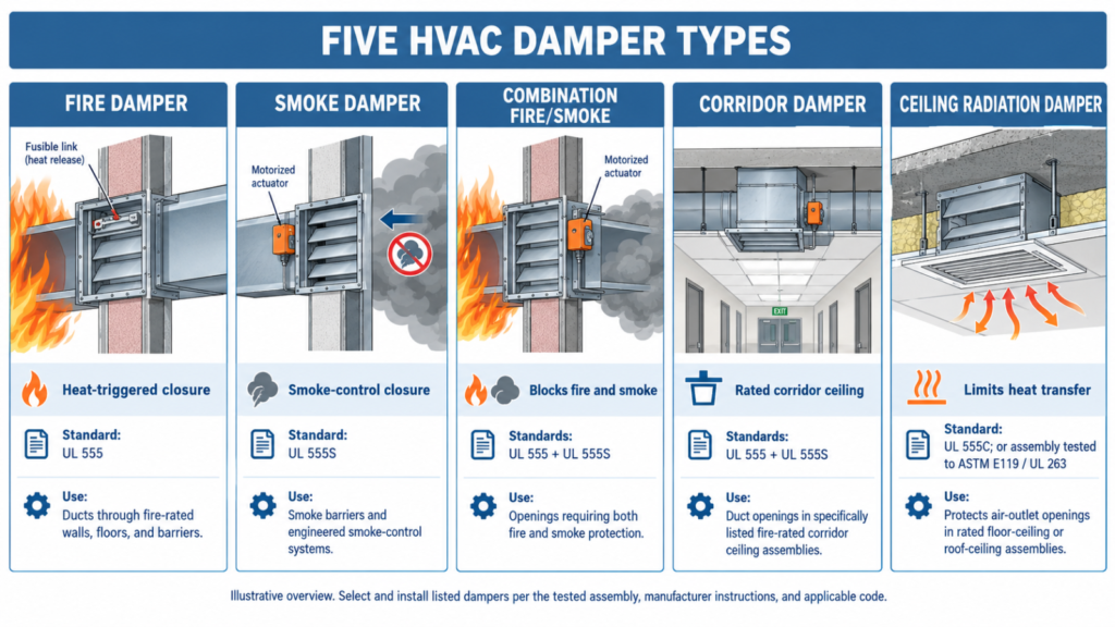
The IBC recognizes five general types of dampers, each tested to a specific standard for a specific application.
| Damper Type | Test Standard | Primary Function | Key Rating |
|---|---|---|---|
| Fire Damper | UL 555 | Restrict passage of flame | Hourly rating (1½ or 3 hour) |
| Smoke Damper | UL 555S | Resist passage of smoke | Leakage class (I, II, or III) and elevated temperature rating |
| Combination Fire/Smoke Damper | UL 555 and UL 555S | Both flame and smoke | Hourly rating plus leakage class |
| Corridor Damper | UL 555 and UL 555S | Protect rated corridors against fire and smoke passage | Hourly rating plus leakage class |
| Ceiling Radiation Damper | UL 555C | Protect floor-ceiling and roof-ceiling assemblies | Assembly component |
Key point: The damper type must match the assembly being protected. A fire damper is not a smoke damper. A static damper is not a dynamic damper.
Key Article: Article 131, Fire-Resistance-Rated Assemblies and UL Listings
Pro Tip: The IBC specifies which damper type is required at each location in Section 717.5 (walls) and Section 717.6 (horizontal assemblies). Start there, not with the damper catalog.
◆ Section 4: Fire Dampers: Static vs. Dynamic, Construction, and Actuation
A. Static Fire Dampers
Static fire dampers are intended for use in static systems, meaning HVAC systems that automatically shut down in the event of a fire. When airflow stops, the damper can close fully.
B. Dynamic Fire Dampers
Dynamic fire dampers are intended for use in dynamic systems, meaning HVAC systems that continue to operate during a fire. The damper must be capable of closing against the air velocity and pressure produced by the system fan.
Dynamic dampers must be tested and labeled for closure under the anticipated airflow and pressure conditions. They may also be used in static systems, but static dampers may not be used in dynamic systems.
C. Airflow and Pressure Ratings
Dynamic fire dampers are marked with airflow and closure pressure ratings. These ratings represent the maximum airflow and closure pressure the damper is tested to perform at.
| Rating | Marking | Minimum |
|---|---|---|
| Airflow rating | 1,000 fpm increments | 2,000 fpm |
| Closure pressure rating | 2-inch w.g. increments | 4-inch w.g. |
The mechanical designer specifies the minimum required airflow and pressure ratings on the mechanical plans. The inspector compares those values to the labeled ratings on the damper.
D. Fire Damper Hourly Rating
Fire dampers must have the minimum rating specified in IBC Table 717.3.2.1 (or IMC Table 607.3.2.1):
| Type of Penetration | Minimum Damper Rating |
|---|---|
| Less than 3-hour fire-resistance-rated assemblies | 1½ hour |
| 3-hour or greater fire-resistance-rated assemblies | 3 hour |
E. Construction and Orientation
Fire dampers are generally one of two constructions:
- Curtain-type: The blades stack out of the airstream when open (or are partially in it), giving low pressure drop. These are common in rectangular ducts.
- Multi-blade: The blades remain in the airstream when open, which adds pressure drop and noise. The designer must account for this in fan selection.
Dampers are listed for specific mounting orientations (horizontal or vertical airflow, vertical or horizontal wall or floor). A damper installed in an orientation not shown in its listing may not close reliably, particularly if it relies on gravity.
F. Actuation Temperature
Fire dampers close when a heat-responsive device, usually a fusible link, releases. The code requires the actuating device to operate at roughly 50°F above the maximum normal system operating temperature, and not less than 160°F. Standard fusible links are commonly rated at 165°F. Higher-rated links (such as 212°F) are used where normal duct temperatures are elevated. Using a higher-rated link than needed delays closure.
Key point: A static damper installed in a system that continues to operate during a fire will not close. The airflow holds the blades open. The rated wall becomes an open hole.
Pro Tip: Verify the system’s operating mode during a fire before selecting the damper. If the fan stays on, the damper must be dynamic and rated for the system’s airflow and pressure.
◆ Section 5: Smoke Dampers and Leakage Class
Smoke dampers are designed to resist the passage of smoke. They are operated by electric or pneumatic actuators and controlled by smoke detectors and/or the fire alarm system. Unlike fire dampers, smoke dampers do not rely on a fusible link.
A. Leakage Class
Smoke dampers are identified by leakage class (Class I, II, or III), based on the amount of air leakage through the closed damper per square foot of damper area at the rated pressure differential.
| Class | Approximate Maximum Leakage (cfm/ft²) |
|---|---|
| Class I | 8 |
| Class II | 20 |
| Class III | 50 |
The IBC requires a leakage rating of not less than Class II. Verify the exact test pressure and values on the damper’s listing.
B. Elevated Temperature Rating
Smoke dampers are also rated for the elevated temperature at which the actuator and damper must still operate. The IBC requires a rating of at least 250°F. Common listed ratings are 250°F, 350°F, and 450°F. Dampers in smoke control systems may need higher ratings.
C. Closing Time
UL 555S limits the time a smoke damper may take to open and close. Slow-acting actuators or undersized pneumatic supply can cause a damper to miss its performance window.
D. Installation Distance
Smoke dampers must be installed in accordance with their listing and the manufacturer’s instructions. The usual rule is that they are placed no more than 24 inches from the smoke barrier they protect, except where used to isolate air handling units. Verify the exact language in the edition adopted.
E. Smoke Damper Actuation
Smoke dampers are controlled by smoke detection. The specific actuation method depends on the application:
| Condition | Actuation Method |
|---|---|
| Smoke damper in a corridor wall or ceiling | May be controlled by a smoke detection system installed in the corridor |
| Smoke damper in a duct served by an HVAC system with total-coverage smoke detection | May be controlled by the smoke detection system |
| Smoke damper in a duct without total-coverage detection | Duct smoke detector (listed for duct use) located to sense smoke at the damper |
| Smoke damper in an air transfer opening | Spot-type detector within 5 feet horizontally |
Key point: The smoke damper must be connected to the detection system that will actuate it. A damper that is installed but not connected to detection is not a smoke damper. It is a manual damper.
Pro Tip: Verify the smoke damper actuation method against the IBC and the fire alarm design. The damper and the detection must be designed together.
◆ Section 6: Combination Fire/Smoke Dampers
Combination fire/smoke dampers meet the requirements of both UL 555 and UL 555S. They are used where a wall, floor, or ceiling requires both a fire damper and a smoke damper.
| Feature | Requirement |
|---|---|
| Listings | UL 555 (fire) and UL 555S (smoke) |
| Actuation | Heat (duct temperature) and smoke (detector or fire alarm signal) |
| Leakage rating | Class I or II (the IBC minimum is Class II) |
| Installation | In a sleeve within the plane of the rated assembly |
Key point: A combination damper is not two dampers in one housing. It is a single device tested to both standards. It must be listed for both.
Pro Tip: Combination fire/smoke dampers are available with electric heat release devices instead of fusible links. Electric release devices are resettable and allow the damper to close in a controlled manner rather than slamming closed.
◆ Section 7: Ceiling Radiation Dampers
Ceiling radiation dampers protect floor-ceiling and roof-ceiling assemblies where ducts penetrate the ceiling membrane.
A. UL 555C
Ceiling dampers are tested to UL 555C. The standard evaluates the damper as a component of a specific hourly rated assembly, not as a standalone device with an hourly rating.
B. Static vs. Dynamic Ceiling Dampers
Ceiling dampers are investigated for dynamic closure where the HVAC system operates during a fire (for example, smoke control systems). Where airflow is stopped at the start of a fire, dynamic closure is not required.
Important limitation: As of the 2018 IBC/IMC code development cycle, there were no UL-listed dynamic ceiling radiation dampers. Static ceiling dampers can therefore only be used where the system is designed to shut down upon detection. Verify current availability in the UL product directory.
C. Actuation
Where a static ceiling radiation damper is installed, a smoke detector must be installed inside the duct, or outside it with sampling tubes, within 5 feet of the damper. Air outlets and inlets must not be located between the detector and the damper.
Key point: Ceiling radiation dampers are assembly components, not standalone rated devices. The assembly rating depends on the damper being installed per the listing.
Pro Tip: For systems that must operate during a fire (exhaust, 100% outside air), verify whether a dynamic ceiling damper is available. If not, the system design may need to change to allow a static damper.
◆ Section 8: Installation Requirements
Damper installation is governed by the listing and the manufacturer’s instructions. The SMACNA Fire, Smoke and Radiation Damper Installation Guide for HVAC Systems is a widely used reference. Several requirements are common across damper types.
A. Sleeves and Clearances
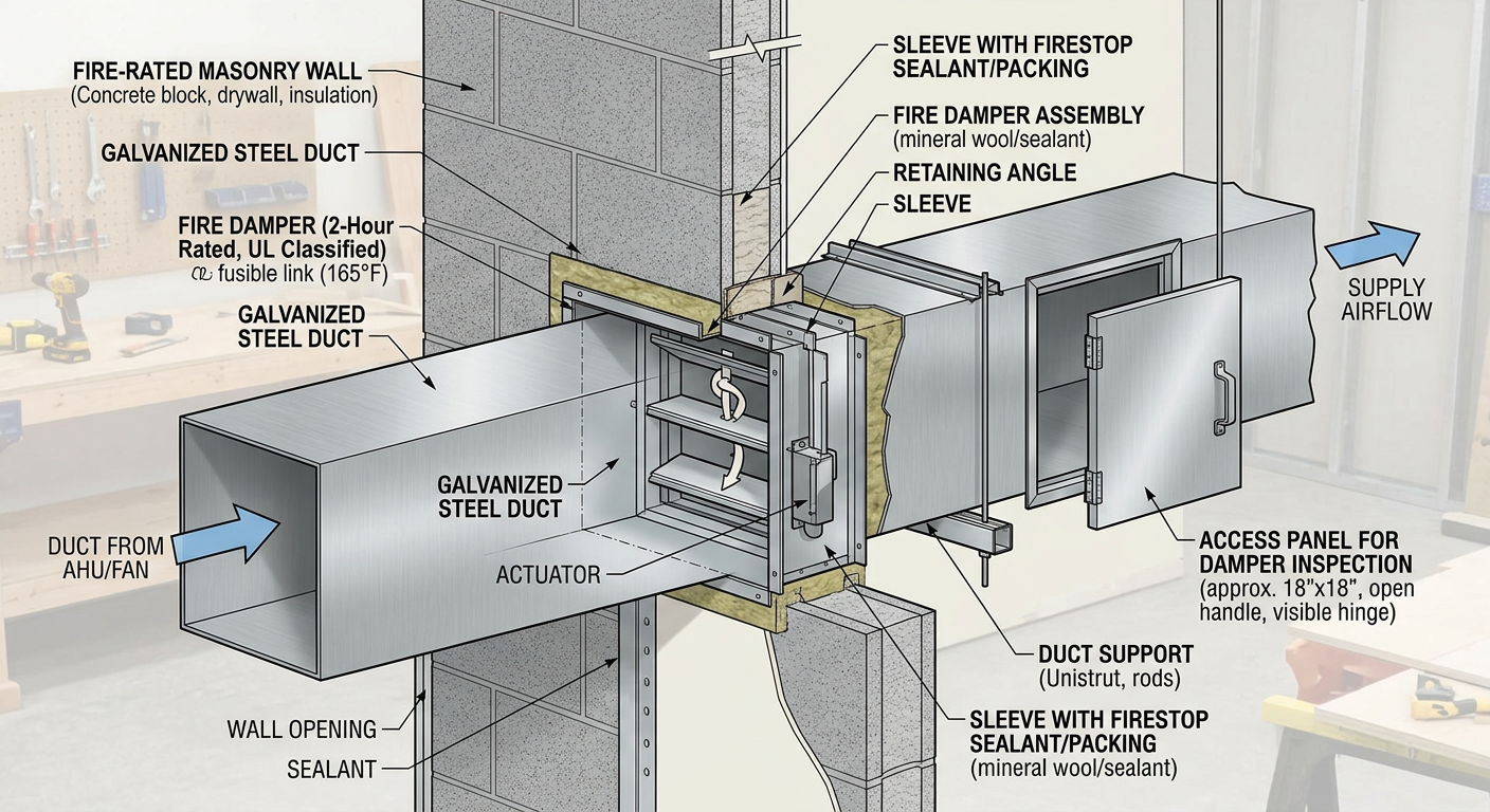
Fire dampers and combination fire/smoke dampers are required to be installed in a sleeve (unless the listing says otherwise) and within the plane of the rated assembly. Smoke damper sleeve requirements depend on the listing and the manufacturer’s instructions.
The opening clearance is typically a minimum of 1/4 inch larger than the damper/sleeve assembly, increasing 1/8 inch for each foot the damper exceeds 24 inches. Always verify against the manufacturer’s instructions, because this allowance accommodates thermal expansion during a fire.
B. Retaining Angles
Retaining angles are installed on both sides of the wall or floor and must overlap the partition by the minimum dimension in the installation instructions (typically 1 inch or more). They must be fastened as the instructions require. The angles hold the damper in the opening and let it expand without distorting the assembly.
C. Breakaway Connections
Fire damper installations typically require breakaway connections between the sleeve or damper and the attached duct. In a fire, ductwork can sag or collapse. A rigid connection can pull the damper out of the opening and destroy the rated assembly. The breakaway connection lets the duct fall away while the damper stays in place. Using rigid duct connections or the wrong fastener type is a common field error.
D. Sealing
The joints between the damper frame and the duct must be sealed to prevent air leakage. Sealant between the mounting angles and the partition is not required by UL but may be specified.
E. Duct Insulation and Wrap
Duct insulation, liner, or wrap passing through the damper area can interfere with blade or curtain movement and can alter the assembly’s performance. Follow the listing for how insulation terminates at the damper.
F. Actuator Access
The actuator and accessories must be accessible for testing, service, or replacement. Coordinate actuator location (and which side of the damper it sits on) with the access panel.
G. Firestopping the Annular Space
The annular space around the damper sleeve must be firestopped with a listed system, just like any other penetration. The firestop and the damper are separate systems, and both must be compliant.
Key point: The installation instructions are part of the listing. A damper installed in a configuration not shown in the manufacturer’s instructions is not a listed installation.
Key Article: Article 134, Firestop Systems: Testing, Listings, and Inspection
Pro Tip: Photograph each damper installation before the ceiling closes. The sleeve, retaining angles, breakaway connection, and firestop are hard to verify later.
◆ Section 9: Access Panels and Identification
Dampers must be accessible for inspection and maintenance.
A. Access Requirements
Fire dampers shall be provided with an approved means of access large enough to permit inspection and maintenance of the damper and its operating parts. The access openings shall not reduce the fire-resistance rating of the building assembly.
B. Labeling
Access points shall be permanently identified on the exterior by a label with letters not less than 0.5 inch in height reading “FIRE DAMPER,” “SMOKE DAMPER,” or “FIRE/SMOKE DAMPER,” as applicable.
Access doors in ducts shall be tight-fitting and suitable for the required duct construction.
Key point: The access panel is the only way to verify the damper works. A damper without access is a damper that will never be inspected.
Pro Tip: Access panels are frequently obstructed by ceiling tiles, insulation, or stored materials. The label exists so that building occupants and maintenance staff can find the damper when they need to.
◆ Section 10: Controls, Detection, and Fire Alarm Integration
Smoke dampers and combination dampers work only if the control system tells them to close.
A. Duct Smoke Detection (NFPA 90A)
NFPA 90A requires duct smoke detectors in many HVAC systems (for example, supply systems above a size threshold) to shut down fans and prevent smoke recirculation. Where those detectors also control dampers, the design must define which detector closes which damper.
B. Fire Alarm Interface (NFPA 72)
Damper control and monitoring must be coordinated with the fire alarm system:
- Duct smoke detectors typically initiate a supervisory or alarm signal at the control panel, depending on the design and the AHJ.
- Dampers may be commanded closed by the detector, by the fire alarm control unit through a control module, or both.
- End switches or position indicators can report damper position to the panel or building automation system.
- Fire alarm and HVAC controls contractors must agree on who supplies and wires the control and monitor modules.
C. Fail-Safe Operation
Smoke damper actuators are normally spring-return to the closed position on loss of power or air. The design should confirm that loss of power does not leave a damper open, and that actuator power (and pneumatic supply, if used) is reliable.
D. Reset After Activation
After a detector trips or a test closes a damper, the damper and detector must be reset and restored to normal. Dampers left closed or detectors left in trouble disable HVAC service, and dampers left open disable protection. A reset procedure should be part of the testing protocol.
Key point: Damper control is a fire alarm and HVAC coordination problem. It is rarely owned by one trade.
Key Article: Fire Alarm System Zoning and Addressable Design (NFPA 72)
Pro Tip: Include a damper control matrix in the drawings listing every damper, its detector, its control method, and what signal it sends to the panel.
◆ Section 11: Dampers in Smoke Control Systems
Engineered smoke control systems (stair pressurization, atrium exhaust, zoned smoke control) use dampers as active components. They are designed under IBC Section 909 and NFPA 92, not just as passive protection.
Key differences from ordinary smoke dampers:
- The damper may need to open on a smoke control signal as well as close.
- Dampers may need to operate against system fan pressure, so a dynamic rating becomes critical.
- Opening and closing times, position verification, and elevated temperature ratings are verified during commissioning.
- Smoke control systems have their own periodic testing requirements (dedicated systems are typically tested more frequently than nondedicated ones), which are separate from the NFPA 80/105 damper testing cycle.
Key point: A damper that is part of a smoke control system is tested as part of that system. Passing a stand-alone damper test does not satisfy the smoke control acceptance requirement.
Key Article: Smoke Control System Design and Testing (NFPA 92) and Stair Pressurization and Smoke Control in High-Rises
Pro Tip: Identify smoke control dampers separately in the damper schedule so they are tested and documented under the correct protocol.
◆ Section 12: Acceptance Testing and Special Inspection
Dampers should be tested before the building is occupied, not only years later.
- Acceptance testing: Each damper is operated in place, with the actuator or release device triggered, and closure is verified. For dynamic dampers, closure under design airflow should be verified where the system design requires it.
- Special inspection: The IBC special inspection provisions cover fire-resistant penetrations and joints (firestopping) and smoke control systems. Check what your jurisdiction requires for dampers and their firestop.
- Closeout documentation: Test reports should identify each damper by location and ID, the date, the tester, and the result.
The first periodic test under NFPA 80/105 is measured from acceptance, so a clean acceptance record also starts the maintenance clock.
Key point: If a damper has never been operated, no one knows whether it works.
Pro Tip: Do acceptance testing before the ceiling is closed and before final firestopping, so any problem can be fixed without demolition.
◆ Section 13: Inspection, Testing, and Maintenance
Dampers require periodic inspection and testing after installation.
A. NFPA 80 and NFPA 105
NFPA 80 governs the installation, testing, and maintenance of fire dampers. NFPA 105 covers smoke dampers. Chapter numbers have changed between editions (for example, the fire damper chapter in NFPA 80 moved from Chapter 19 to Chapter 20 in some editions), so confirm the current chapter in the edition adopted.
2025 edition changes: Both standards were revised in 2025 with new requirements for operability, prevention of blockage, replacement of dampers, visual inspection using remote methods, and a performance-based design option for inspection, testing, and maintenance.
B. Testing Frequency
For fire dampers, the 2019 NFPA 80 established the following frequency:
| Timing | Frequency |
|---|---|
| Initial | 1 year after acceptance testing |
| Subsequent | Every 4 years |
| Hospitals | Every 6 years |
The 2025 editions include provisions for remote inspection methods where dampers are equipped for it, but the requirement for periodic physical inspection remains a point of debate. Smoke dampers have comparable intervals under NFPA 105, and dampers in smoke control systems follow the more frequent smoke control testing requirements. Confirm the intervals your AHJ enforces.
C. What Testing Involves
Damper testing involves:
- Visual confirmation of proper operation
- Operating the damper via the actuator or releasing the fusible link (where applicable)
- Verifying closure (or opening, where applicable)
- Checking for rust, blockage, or damage
- Verifying that the damper fully re-opens or is reset after the test
- For dynamic dampers, verifying closure under airflow where required
If the damper is not operable, repairs shall begin without delay.
D. Qualified Personnel
Testing should be performed by people trained to inspect and test dampers, with the knowledge to recognize damaged links, seized blades, and installation deviations.
Key point: Testing is not a visual check from a distance. The damper must be operated and observed. A damper that “looks fine” may be seized.
Pro Tip: Remote inspection via damper position indicators is permitted in some editions, but it does not replace physical inspection for detecting rust, blockage, or damage. Verify what your AHJ accepts.
◆ Section 14: Documentation, Replacement, and Modification
A. Records
Keep a damper register listing each damper’s ID, location, type, rating, actuation method, and test history. Keep the listing label data and installation details with it. The register becomes the roadmap for every future inspection.
B. Replacement
When a damper or actuator is replaced, the replacement should match the original listing for rating, type (static or dynamic), leakage class, temperature rating, and installation method. A cheaper or different unit can quietly change the assembly’s performance.
C. Modifications and Renovations
Duct modifications, new insulation, added grilles, changes to the HVAC operating mode, and ceiling renovations can all affect dampers. A system that was shut down during a fire when installed, but is later changed to run continuously, may need dynamic dampers it never had.
Key point: Dampers should be reviewed whenever the HVAC system, the assembly, or the building use changes.
Pro Tip: Add a “damper review” line to the renovation permit checklist.
◆ Section 15: Common Mistakes and How to Avoid Them
| Mistake | Why It’s a Problem | How to Fix |
|---|---|---|
| Static damper in a dynamic system | Airflow holds blades open; damper does not close | Verify system operating mode; specify dynamic damper |
| Damper omitted where an exception was assumed | Exception conditions not actually met | Confirm each exception against the code edition and assembly |
| Smoke damper installed too far from barrier | Leakage path bypasses the damper | Install within the distance required by the listing and code |
| Rigid duct connection (no breakaway) | Duct can pull the damper out of the wall in a fire | Use breakaway connections per the manufacturer’s instructions |
| Damper installed in the wrong orientation | Damper may not close reliably | Match the mounting orientation in the listing |
| Fusible link rating too high | Closure delayed past the intended temperature | Select the link per system temperature and code limits |
| No access panel | Damper cannot be inspected or maintained | Provide labeled access panel; verify accessibility |
| Access panel obstructed | Damper effectively inaccessible | Coordinate access with ceiling and finishes |
| Damper not connected to detection | Smoke damper does not actuate | Verify actuation method and connection |
| No fire alarm/HVAC coordination | Neither trade installs the control or monitor module | Provide a damper control matrix |
| Improper sleeve or clearance | Installation not per listing | Follow manufacturer’s installation instructions |
| Annular space not firestopped | Rating lost at penetration | Install listed firestop system |
| No acceptance testing | Failures discovered years later | Test every damper before occupancy |
| No periodic testing | Damper may be seized when needed | Implement testing schedule per NFPA 80/105 |
| Assuming remote inspection is sufficient | Rust, blockage, and damage not detected | Physical inspection at required intervals |
| Replacement with a non-matching unit | Rating, type, or leakage class changed | Replace with the same listing and document it |
◆ Section 16: Conclusion
Fire dampers and smoke dampers are the critical link between HVAC systems and fire-rated assemblies. They protect duct penetrations through rated walls and floors, and they prevent smoke migration through ductwork.
The IBC establishes where dampers are required. UL 555, UL 555S, and UL 555C establish the ratings that determine whether a damper can perform its function. NFPA 90A and NFPA 72 govern detection and fire alarm integration. NFPA 80 and NFPA 105 establish how dampers are inspected, tested, and maintained after installation.
A damper is a mechanical device. It has moving parts, and moving parts fail. The rated assembly it protects is only as good as the damper’s installation, controls, and maintenance.
Key Takeaways:
- The IBC specifies the damper type required at each location in Section 717.5 (walls) and Section 717.6 (horizontal assemblies). Exceptions are narrow and conditional.
- Fire dampers are not permitted in Type I kitchen hood grease ducts.
- Static vs. dynamic is critical. A static damper in a system that operates during a fire will not close.
- Dynamic dampers are marked with airflow and closure pressure ratings that must meet or exceed the system design.
- Fire damper hourly rating is 1½ hour for less than 3-hour assemblies and 3 hour for 3-hour or greater.
- Fusible links operate at about 50°F above maximum system temperature and not less than 160°F (commonly 165°F).
- Smoke dampers are rated by leakage class (minimum Class II under the IBC) and elevated temperature (minimum 250°F), and must be installed per the listing and code distance rule.
- Combination fire/smoke dampers must be listed to both UL 555 and UL 555S.
- Ceiling radiation dampers are tested to UL 555C as assembly components.
- Breakaway connections let ductwork fall away without pulling the damper from the wall.
- Dampers must be tied to detection and the fire alarm system, and smoke control dampers are tested as part of the smoke control system.
- Access panels must be provided and labeled “FIRE DAMPER,” “SMOKE DAMPER,” or “FIRE/SMOKE DAMPER.”
- Test dampers at acceptance, then under NFPA 80/105 (1 year after acceptance, then every 4 years, or every 6 years for hospitals). Verify the intervals your AHJ enforces.
- Remote inspection does not replace physical inspection for detecting rust, blockage, or damage.
Take Action Today:
- Verify the damper type required at each rated penetration, and check any claimed exceptions.
- Confirm whether the system is static or dynamic, and specify dampers accordingly.
- Verify dynamic damper airflow and pressure ratings against system design.
- Confirm smoke dampers are placed per the listing and the code distance rule.
- Verify breakaway connections, sleeve, retaining angles, and clearances against the installation instructions.
- Verify access panels are provided, labeled, and accessible.
- Confirm each damper is connected to the correct detection and fire alarm control.
- Perform and document acceptance testing before occupancy.
- Implement the NFPA 80/105 testing schedule and keep a damper register.
- Train maintenance staff on damper operation and inspection.
- Coordinate firestop and damper installations as separate but complementary systems.
Continue Reading from Our Series:
-
Related guide: Fire-Resistance-Rated Assemblies and UL Listings (Article 131)
-
Learn more: Firestop Systems: Testing, Listings, and Inspection (Article 134)
-
Read more: Grease Duct Design and Fire Safety (Article 135)
[End of Article]