IMPORTANT DISCLAIMER: This guide references ASTM E119, Standard Test Methods for Fire Tests of Building Construction and Materials; UL 263 (ANSI/UL 263); the International Building Code (IBC), Chapter 7 (Fire and Smoke Protection Features); and the UL Fire Resistance Directory. Codes and standards vary by edition and are frequently amended by states and localities. ASTM E119-26 is the current edition of the test method, but the edition adopted by your jurisdiction may be older. UL 263 is harmonized with ASTM E119. NFPA 251 was withdrawn as an active standard. Local amendments and the edition adopted by your Authority Having Jurisdiction (AHJ) always control. This guide is a starting point only. Always verify requirements with your AHJ.
Edition note: Section numbers in this guide follow the IBC as renumbered starting with the 2012 edition. Readers working with the 2009 IBC or earlier will find most Chapter 7 sections numbered one lower (for example, opening protectives were IBC 715, now 716; fire barriers were 706, now 707; smoke barriers were 708, now 709). Fireblocking and draftstopping are consolidated at IBC 718 in current editions.
Fire-resistance-rated assemblies are the backbone of passive fire protection. They slow fire spread, protect structural elements, and compartmentalize buildings. Unlike active systems such as sprinklers, alarms, and suppression, rated assemblies have no moving parts and need no power. They work by design, and they fail when construction deviates from the tested listing.
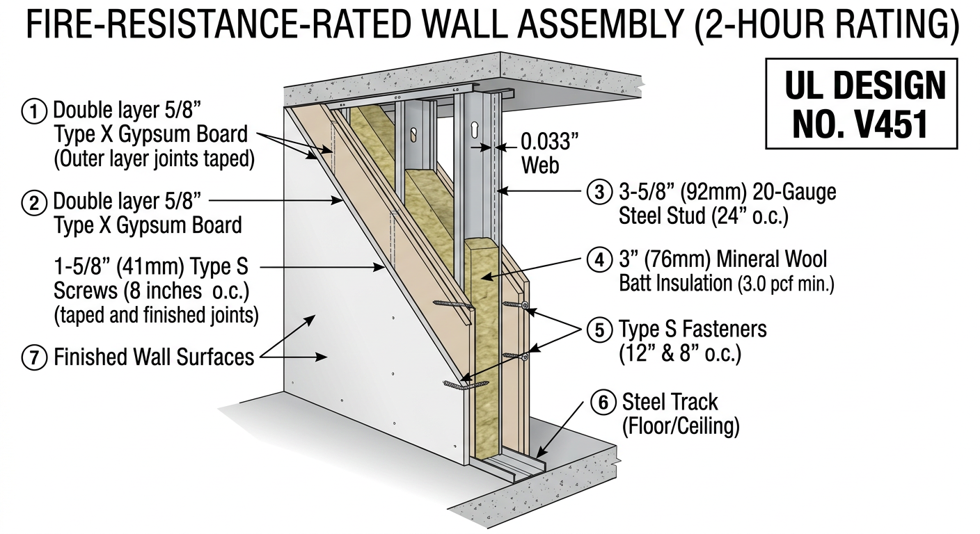
That is the core challenge: the rating belongs to the assembly as tested, not to its individual components. A wall rated for 2 hours holds that rating only if every component matches the listing: gypsum board type and thickness, stud gauge and spacing, fastener type and spacing, and insulation. Substitute one component without a sound basis, and the rating is in doubt.
This article covers testing standards, UL listings, how ratings are established, restrained vs. unrestrained classification, and the field verification that determines whether a rated assembly performs as designed.
◆ Section 1: Why Fire-Resistance Ratings Matter
| Function | What the Rating Accomplishes |
|---|---|
| Structural protection | Delays collapse of columns, beams, and floor assemblies |
| Compartmentation | Limits fire spread between occupancies and areas |
| Egress protection | Protects corridors, stairways, and exit passageways |
| Separation | Provides rated separations between different occupancies |
Key point: Fire-resistance ratings are expressed in hours (commonly 1, 1½, 2, 3, 4) and represent the time an assembly withstands the standard test exposure while meeting the applicable acceptance criteria. Those criteria depend on the assembly type (see Section 2).
Key Article: Article 45 — Occupancy Separation Requirements (NFPA 101 Table 6.1.14.4.1)
Pro Tip: The rating is not a prediction of how long the assembly will survive a real fire. It is a comparative measure under standard test conditions. Applying test results to actual buildings requires evaluating actual conditions.
◆ Section 2: Testing Standards
A. ASTM E119 / UL 263
ASTM E119 is the primary test method for fire-resistance testing of building construction. UL 263 is the harmonized UL counterpart, and the two are used interchangeably in the IBC.
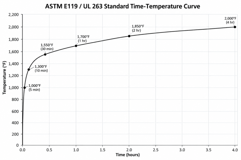
The test follows a standard time-temperature curve:
| Time | Temperature (°F) | Temperature (°C) |
|---|---|---|
| 5 minutes | 1,000°F | 538°C |
| 10 minutes | 1,300°F | 704°C |
| 30 minutes | 1,550°F | 843°C |
| 1 hour | 1,700°F | 927°C |
| 2 hours | 1,850°F | 1,010°C |
| 4 hours | 2,000°F | 1,093°C |
The test evaluates:
-
Heat transmission through the assembly (temperature rise on the unexposed side)
-
Structural load-carrying capacity during exposure (for loadbearing assemblies)
-
Integrity (passage of flames or hot gases, ignition of cotton waste)
-
Hose stream resistance (applied to walls and partitions, not to every element type). The hose stream is applied immediately after the fire exposure period, on the same specimen or a duplicate depending on the rating and the standard’s requirements. For some higher ratings or element types, the stream is applied to a duplicate (unexposed) specimen per the standard’s conditioning rules, which is why some listings show separate fire and hose-stream ratings. Readers frequently assume the same specimen takes both.
For walls and floors, the typical temperature criteria are an average rise of 250°F (139°C) on the unexposed surface, with a 325°F (181°C) rise at any single point. Columns and beams are judged mainly on load-carrying capacity and steel temperature limits rather than unexposed-surface rise.
B. NFPA 251
NFPA 251 was the NFPA fire endurance standard. It was withdrawn in Fall 2010, and ASTM E119 / UL 263 are the primary methods.
C. What the Test Does Not Measure
The test does not assess suitability under conditions other than the standard fire, and it does not predict performance after fire exposure. Real fires vary in fuel load, ventilation, and compartment size. Fire testing is a comparative tool, not an absolute predictor.
Key point: The test standard and the listing are different things. ASTM E119 defines the test. The UL Fire Resistance Directory publishes the specific assemblies that passed and the construction details required.
◆ Section 2D: Fire Metrics That Are NOT Fire-Resistance Ratings
Three fire-performance measures are routinely confused with hourly ratings. Confusing them produces noncompliant construction even when every product is “rated” for something.
| Metric | Test Standard | What It Measures | Typical Use | Common Confusion |
|---|---|---|---|---|
| Fire-resistance rating | ASTM E119 / UL 263 | Time to failure under standard fire | Walls, floors, columns, shafts | (the subject of this article) |
| Flame spread / smoke developed index | ASTM E84 / UL 723 | Surface burning characteristics | Interior wall/ceiling finish (Class A/B/C) | A “Class A finish” is NOT a rated wall |
| Roof covering classification | ASTM E108 / UL 790 | Resistance of the covering to external fire (flame spread, intermittent flame, burning brand) | Roof coverings (Class A/B/C) | A “Class A roof” is NOT a fire-resistive roof assembly |
Key point: Interior finish, roof covering, and fire resistance are three independent compliance tracks. A corridor wall with Class A paint but no listed assembly is still unrated; a roof with a Class A membrane over unprotected structure may still need a rated deck and supports.
Pro Tip: When reviewing submittals, watch for datasheets that lead with an ASTM E84 or UL 790 classification as if it were a fire-resistance rating. Vendors do this constantly with coatings, insulation facings, and single-ply membranes.
◆ Section 2E: Other Fire Curves and International Equivalents
The ASTM E119 curve is a cellulosic curve, developed for ordinary combustible building contents. Structures exposed to flammable-liquid pool fires are evaluated against the UL 1709 hydrocarbon curve, which rises far faster. An E119 rating does not substitute for a UL 1709 rating in petrochemical or fuel-handling structures, and vice versa.
International equivalents include ISO 834 (cellulosic curve, near-identical to E119), EN 13501-2 classifications (EI ratings), BS 476 Parts 20–22 (largely superseded but still cited on legacy documentation), and CAN/ULC S101 under Canada’s National Building Code. Ratings from one system are not interchangeable with another: an “EI 60” dossier does not automatically satisfy a 1-hour IBC requirement, and product listings must be matched to the jurisdiction’s adopted standard. Confirm equivalency with your AHJ.
◆ Section 3: How Fire-Resistance Ratings Are Established
IBC Section 703.3 recognizes several methods of establishing a rating [verify section numbers by edition]:
| Method | Description |
|---|---|
| Tested assemblies | Listed designs from UL, Intertek, and others, tested per ASTM E119 / UL 263 |
| Prescriptive designs | Generic assemblies in IBC Section 721 |
| Calculated fire resistance | Calculation methods in IBC Section 722, including ASCE/SEI/SFPE 29 |
| Engineering analysis | Analysis based on ASTM E119 test data, such as extensions under ASTM E2032, accepted by the building official |
Listed designs are the most common route for practitioners and are the focus of this article. Prescriptive and calculated methods are useful for concrete and masonry, but they are not substitutes for listed assemblies where a listing exists for the application.
Fire-resistance rating vs. fire-protection rating: These are different. A fire-resistance rating applies to walls, floors, roofs, beams, and columns. A fire-protection rating applies to opening protectives such as doors, shutters, and windows (tested under NFPA 252, NFPA 257, UL 10B/10C), and fire dampers are tested separately (UL 555). An opening protective does not carry the wall’s fire-resistance rating, and the code sets how the two ratings relate.
◆ Section 4: The UL Fire Resistance Directory
UL’s Fire Resistance Directory is a leading source of listed assemblies. Intertek also publishes listings, and the Gypsum Association’s Fire Resistance and Sound Control Design Manual (GA-600) collects gypsum-based designs.
A. Assembly Design Numbers
Each tested assembly has an alphanumeric design number. The prefix letter indicates the group of construction [verify against the current UL Guide Information]:
| Prefix | Group of Construction |
|---|---|
| A, B, C | Floor-ceiling: concrete with cellular steel floor units |
| D, E, F | Floor-ceiling: concrete with steel floor units |
| G, H, I | Floor-ceiling: concrete and steel joists |
| J or K | Floor-ceiling: precast and field-poured concrete |
| L | Floor-ceiling: wood or combination wood and steel joist |
| N | Beam designs for floor-ceiling assemblies |
| P | Roof-ceiling designs |
| S | Beam designs for roof-ceiling assemblies |
| U, V, or W | Wall and partition designs |
| X or Y | Column designs |
Note: The prefix letter is an organizational legacy, not a performance indicator. A “U” wall and a “W” wall of the same rating are not interchangeable, and some letter ranges (such as U/V/W) contain both loadbearing and nonbearing designs. The listing itself must always be read.
B. Finding the Right Design
UL Product iQ is the current tool for accessing UL fire-resistance designs. Registration is free. Listings are searched by design number, rating, or product category (BXUV is the key category for ANSI/UL 263 assemblies).
Key point: The design number is the specification. The assembly must be built as described, component by component, dimension by dimension.
Pro Tip: UL permits designers to transfer assembly specifications into construction documents. Check UL’s current terms of use.
◆ Section 5: Assembly Components and Construction Requirements
A. Component Specificity
Each UL design specifies:
-
Gypsum board: type, thickness, and number of layers
-
Studs: size, gauge, spacing, and material
-
Fasteners: type, length, and spacing
-
Insulation: type, thickness, and density (where required)
-
Protective materials: spray-applied fire-resistive materials (SFRM) and intumescent coatings, by type and thickness
Exception: UL General Information permits certain substitutions. For example, screws meeting ASTM C1002 or C954 may replace nails if head diameter, length, and spacing equal or exceed those specified, subject to the General Information conditions.
B. Gypsum Board Orientation
-
Vertical application: long edges parallel to framing members.
-
Horizontal application: long edges perpendicular to framing members.
Orientation and joint staggering are specified in the design and matter to the rating.
C. Gypsum Board Type
“Type X” and “Type C” boards are defined by ASTM C1396 and have specific fire-resistance properties. Many designs require a specific proprietary board, and not every Type X board qualifies. Verify the manufacturer, product, and thickness against the listing, including the board’s marking.
D. Minimums and Maximums
-
Gypsum board thicknesses are minimums. Greater thickness is permitted if fastener length increases to give equal or greater penetration.
-
Steel stud sizes are minimums unless otherwise stated.
-
Stud spacing is a maximum unless otherwise stated.
-
Metal thicknesses are minimums unless a specific gauge is indicated.
Key point: Know which dimensions are minimums, maximums, or exact.
Key Article: Article 64 — Firestopping and Penetration Sealing — Essential Details
Pro Tip: UL General Information allows additional gypsum layers in many wall designs, but not where a design restricts it, such as some floor-ceiling or loadbearing designs. Removing layers voids the rating.
E. Exposure Side
Many wall designs are rated for exposure from either side. Some designs are rated from one side only. For exterior walls, IBC Section 705 sets whether the wall must be rated for exposure from the inside only or from both sides, depending on fire separation distance. Exterior walls with a fire separation distance greater than 10 feet are rated for exposure from the inside only; walls with a fire separation distance of 10 feet or less must be rated for exposure from both sides.
◆ Section 6: Restrained vs. Unrestrained Assemblies
The restrained/unrestrained classification applies to floors, roofs, and beams. It does not apply to walls or columns.
A. What Restraint Means
Restraint refers to whether the surrounding or supporting structure can resist the thermal expansion of the assembly during a fire.
-
Restrained: supported by structure that resists thermal expansion, for example beams welded, riveted, or bolted to framing, or slabs cast with framing.
-
Unrestrained: free to rotate and expand at its supports.
B. Why It Matters
A restrained classification can permit less fire protection for the same rating, often for steel beams and floors.
| Classification | Fire Protection Required | Typical Construction |
|---|---|---|
| Restrained | Often less | Steel beams welded or bolted to framing; cast-in-place concrete |
| Unrestrained | More | Simply supported beams; precast concrete without restraint |
C. Determining the Classification
IBC §703.2.3 states that assemblies are not considered restrained unless the registered design professional furnishes evidence satisfactory to the building official. The restrained condition must be identified on the construction documents.
Sources for determining restraint:
-
The restraint guidance in UL 263 and in the non-mandatory annex of ASTM E119 (historically Annex X) [verify annex designation by edition]
-
UL Guide Information for Fire Resistance Ratings (BXUV)
Pro Tip: Many project specifications default to “unrestrained” in the rating schedule to avoid the documentation burden. That is a defensible practice, but it should be a deliberate, documented decision—not a silent default—because it typically increases the required protection thickness or rating.
Key point: When in doubt, use the unrestrained rating. It is more conservative and is valid where the assembly is actually restrained.
Pro Tip: Qualified listings often allow a lesser thickness of applied fire protection on steel if a restrained classification is confirmed.
◆ Section 7: Walls, Floors, Roofs, and Columns
A. Wall and Partition Assemblies
Walls and partitions use prefixes U, V, and W. Key components are gypsum board layers, stud size, gauge, and spacing, fasteners, and insulation (optional in many wall designs unless specified).
The IBC groups rated vertical elements by function:
-
Fire walls (IBC 706): structural stability required, since the wall must remain standing if construction on one side collapses
-
Fire barriers (IBC 707): shafts, exit enclosures, occupancy separations
-
Fire partitions (IBC 708): corridors, tenant separations, dwelling units
-
Smoke barriers and partitions (IBC 709, 710): limit smoke movement, with separate rating and opening requirements
-
Horizontal assemblies (IBC 711): floor and roof/ceiling separations
B. Floor-Ceiling Assemblies
Floor-ceiling designs use the A–L prefixes. Components include the structural floor (concrete, steel deck, or wood), the ceiling membrane (gypsum board or sprayed materials), and beams and joists.
Where the ceiling is part of the rated assembly, ceiling penetrations are part of the listing. Recessed light fixtures, air diffusers, and access panels must follow the listed design. Unprotected fixtures can break the membrane.
C. Roof-Ceiling Assemblies
Roof-ceiling designs use prefix P.
D. Column and Beam Protection
Column designs use prefixes X and Y, and beam designs use N and S. Common protection methods are:
-
Spray-applied fire-resistive materials (SFRM)
-
Intumescent coatings
-
Gypsum board enclosures
-
Concrete encasement
For protected steel, required thickness depends on the member’s W/D ratio, which is weight per foot divided by heated perimeter. Light, thin members heat faster and need more protection. SFRM listings also specify density and bond strength, which must be field-verified.
E. Mass Timber
Recent IBC editions added Type IV-A, IV-B, and IV-C construction. These rely on a mix of encapsulation, char calculations, and fire-resistance testing under ASTM E119. Rated mass timber should be evaluated with the designer and AHJ, using the adopted IBC edition.
◆ Section 7F: Opening Protectives — Doors, Frames, and Glazing
Opening protectives are where most rating failures actually occur in finished buildings. Three ideas carry almost the entire topic.
1. Fire-protection ratings pair with wall ratings. The IBC (Chapter 716 in 2012+ editions; 715 in earlier editions) sets required door, shutter, and frame ratings as a function of the wall rating. Ratings are 20, 45, 60, 90, and 180 minutes. A common field error is installing a 20-minute door in a 1-hour stair enclosure because “it’s a rated door.” Specific pairings include:
| Wall Type | Required Door Rating |
|---|---|
| Shaft, exit enclosures (2-hour wall) | 1½-hour door |
| Fire barriers (1-hour wall) | 1-hour door |
| Fire partitions — corridor walls (1-hour wall) | 20-minute (1/3-hour) door |
| Smoke barriers (1-hour) | ¾-hour door |
Verify the pairing table against your adopted IBC edition.
2. Positive pressure vs. neutral pressure. Fire doors are tested to UL 10C (positive pressure), which superimposes a temperature-gradient neutral-plane requirement on the fire exposure; the older UL 10B (neutral pressure) legacy persists in some product literature. Specify UL 10C where the adopted code requires it [verify edition].
3. Fire-protective vs. fire-resistive glazing.
-
Fire-protective glazing (tested to NFPA 257 / UL 9, with hose stream impact—Category A or B) stops flames but does not meet the temperature-rise criteria of ASTM E119. It is permitted only within size and application limits set by the IBC (for example, limited vision panels in certain 1-hour-or-less walls, and sidelights and transoms in 20-minute corridor walls). Hose-stream impact resistance (Category A vs. B) matters at locations subject to hose stream exposure.
-
Fire-resistive glazing (tested to ASTM E119 / UL 263 as a wall or window assembly) can serve in higher-rated walls and larger areas, and its rating must equal or exceed the wall rating.
Key point: Glazing must carry a permanent label showing its rating, standard, and whether it passed the hose stream. Unlabeled or mislabeled “fire glass” in storefronts, borrowed lights, and corridor sidelights is one of the most-cited deficiencies in existing-building surveys.
Supporting details worth specifying:
-
Temperature-rise doors. Doors in stair enclosures and certain other locations must limit heat transmission (T20/T250/T450 temperature-rise labels) so radiated heat does not block egress on the non-fire side [verify required locations by edition].
-
Clearances and hardware. Typical limits: 1/8 inch or less at the head and jambs, 3/4 inch or less at the sill (less where smoke gasketing is required); positive latching; self-closing or automatic-closing; gasketing where required. No field drilling or welding beyond the listing.
-
Labels. The door, frame, and glazing each carry labels. Missing, painted-over, or damaged labels make an otherwise compliant door unverifiable; NFPA 80 governs field labeling and inspection, with annual inspections required.
-
Smoke doors. Governed by NFPA 105. They are leakage-rated (UL 1784), require closers and gasketing within stated limits, but—a frequent design error—do not require positive latching unless they are also fire doors.
-
Fire-rated shutters and counter shutters follow the same pairing logic and are frequently missed in plans review for service counters and pass-throughs in rated walls.
◆ Section 8: Penetrations, Joints, and Firestop Systems
Firestopping restores the rating where construction is interrupted. Each system type has its own test standard:
| Condition | Typical Test Standard | Common Rating Terms |
|---|---|---|
| Through-penetrations | ASTM E814 / UL 1479 | F rating, T rating |
| Fire-resistive joints (head-of-wall, floor-to-floor) | ASTM E1966 / UL 2079 | Hourly rating |
| Perimeter fire barriers (curtain wall to floor) | ASTM E2307 | Hourly rating, integrity |
F rating vs. T rating: An F rating addresses flame passage only. A T rating also limits temperature rise on the unexposed side, and the IBC requires it for certain penetrations (for example, through-penetrations in floors with exceptions). An L rating (air leakage) matters at smoke barriers [verify the IBC section for your edition].
A listed firestop product does not create a compliant installation by itself. The field condition must match the applicable system listing.
Inspectors should verify:
-
Annular space within permitted limits
-
Backing material type and compression
-
Sealant depth that meets the listing
-
Devices and wrap strips positioned correctly
-
Products that match approved submittals
Dampers: Where ducts penetrate rated assemblies, fire dampers (UL 555), smoke dampers (UL 555S), and combination dampers must be installed per the manufacturer’s instructions and listing. Ceiling radiation dampers (UL 555C) are used where ducts or openings pass through the ceiling membrane of a rated floor-ceiling or roof-ceiling assembly.
◆ Section 8A: Membrane Penetrations and Electrical Work
Section 8 covers through-penetrations; membrane penetrations — breaches of only one side of a rated assembly — have their own rules [IBC 714.4 / 714.3 in 2012+ editions; verify by edition], and electrical trades create most of them.
Outlet and device boxes. Rules address metallic vs. nonmetallic boxes, aggregate area limits per wall area, and — the classic failure — boxes installed on opposite sides of the same stud cavity. Unless an approved putty pad or listed enclosure protects them, boxes on opposite sides of the wall must be adequately separated or protected per the code’s methods (commonly a horizontal offset). Electricians almost never know this rule.
Recessed luminaires. An “IC-rated” fixture is an insulation-contact rating, not a fire rating. Where the ceiling membrane is part of a listed floor-ceiling assembly, fixtures must be (a) covered by a listed fire-rated enclosure within the tested design, (b) protected by a listed recessed-fixture cover in a listed system, or (c) addressed in the UL design itself. Distinguish this from ceiling radiation dampers (UL 555C), which serve ducted openings.
Cabling and cable trays. Bundled cable through-penetrations require listed systems sized for the bundle; retrofit cable additions after occupancy are the single largest source of unrated penetrations in commercial buildings. Require the cabling work to be firestopped under the firestop contractor’s supervision, not as an afterthought.
Pro Tip: Put a note on the electrical drawings: “All boxes and fixtures in rated construction per Section X; opposite-side box offsets and putty pads by E-contractor; firestopping by certified firestop contractor.”
◆ Section 8B: Fireblocking and Draftstopping Are Not Firestopping
Three similarly named requirements, three different purposes [IBC 718 in 2012+ editions]:
| Term | Location | Purpose |
|---|---|---|
| Firestopping | Penetrations and joints in rated assemblies | Restore the tested rating (Section 8) |
| Fireblocking | Concealed wood-framed spaces (walls, furred spaces, soffits, stair stringers) | Subdivide combustible concealed spaces to slow flame spread |
| Draftstopping | Attics, floor-ceiling plenums over occupiable spaces | Limit the volume feeding a fire in concealed horizontal spaces |
Key point: A Type V wood building typically needs all three. Fireblocking at wood framing is ordinary lumber or gypsum scraps installed per the code; it has nothing to do with UL systems. Plan reviewers reject permit sets that show rated walls but no fireblocking, and inspectors write it up constantly in multi-family wood construction.
◆ Section 9: Field Verification and Common Failures
The gap between the tested assembly and the installed assembly is where ratings fail.
A. Common Deficiencies
| Deficiency | Why It Affects the Rating |
|---|---|
| Wrong gypsum board type or thickness | Design specifies board and minimum thickness |
| Wrong stud gauge or spacing | Design specifies minimum gauge and maximum spacing |
| Wrong fastener type or spacing | Design specifies fasteners and spacing |
| Missing layers | Design specifies number of layers |
| Unspecified insulation added | In some floor-ceiling assemblies, added insulation can reduce the rating |
| Unprotected ceiling fixtures | Ceiling membrane integrity is lost |
| Unfirestopped penetrations or joints | A listed system is required for each |
| Walls not extended to deck | Many rated walls must continue to the structure above, or a ceiling must be part of the listing |
B. Marking and Identification
IBC Section 703.7 requires fire walls, fire barriers, fire partitions, smoke barriers, and smoke partitions to be identified with signs or stenciling in concealed spaces [verify section number by edition]. Typical wording is “FIRE AND/OR SMOKE BARRIER — PROTECT ALL OPENINGS.” Placement and lettering size are specified by the code.
C. Special Inspection
IBC Chapter 17 requires special inspection of fire-resistant construction elements, including:
-
Firestop penetrations and joints, required in high-rise buildings and Risk Category III and IV buildings
-
Sprayed fire-resistant materials and mastic/intumescent coatings on structural members
ASTM E2174 covers on-site inspection of penetration firestops, and ASTM E2393 covers fire-resistive joint systems and perimeter fire barriers.
D. Engineering Judgments
Where field conditions deviate from tested listings, an Engineering Judgment (EJ) may be developed. EJs should be prepared by:
-
Manufacturer’s qualified technical personnel
-
A knowledgeable registered Professional Engineer
-
A Fire Protection Engineer
-
An independent testing agency
Key point: Use EJs only where no tested and listed system exists for the application. Many AHJs expect EJs to follow the International Firestop Council (IFC) guidelines for evaluating firestop engineering judgments and to be submitted for review.
◆ Section 9E: Applied Fire Protection (SFRM/Intumescent) — Field Quality
Special inspection of SFRM (IBC 1705.14) covers three distinct verifications, and confusion among them causes disputes at substantial completion:
-
Thickness — measured against the listing’s required thickness for that member’s W/D ratio, not a blanket number from the product data sheet. A beam with a different W/D than the drawing schedule carries a different required thickness.
-
Density — ASTM E605; laboratory samples from in-place material.
-
Bond strength — ASTM E736; bond and adhesion failures are the classic SFRM deficiency, especially on shop-applied primers, galvanized surfaces, or where cure conditions were poor.
Also verify: compatibility with shop primers, recoat and cure windows, moisture protection during construction (many cementitious products degrade when wetted before cure), required clips and anchors for cementitious SFRM on decks, and that any topcoat is specifically listed for use over that SFRM. “Equal” substitution of one listed SFRM for another is not permitted without a new listing or an accepted Engineering Judgment — this is a frequent attempted change order.
For intumescent coatings: required dry-film thickness per the listing, stripe coats on edges and flanges, and surface preparation per the manufacturer. DFT is checked with wet-film and cured-coating measurements; undocumented thinning is a known failure mode.
◆ Section 9F: Firestop Program Quality
A listed product does not create a compliant installation — the corollary deserves its own treatment:
-
Certified contractors. The UL Qualified Firestop Contractor Program and FM 4991 (Approval of Firestop Contractors) provide third-party auditing of a contractor’s training, methods, and documentation. Many specifications and some AHJs now require one of them, and they materially reduce inspection findings.
-
Penetration schedule. Require the firestop submittal to be organized by condition (metallic pipe sizes, plastic pipe types and sizes, cable bundles, mixed penetrations, joints with movement), matching the project matrix — not a product cut-sheet dump.
-
Inspection. ASTM E2174 (penetrations) and ASTM E2393 (joints and perimeter) define visual inspection and destructive verification (sampling of installed systems per the referenced sampling standard). Destructive verification is required by IBC special inspection provisions for firestopping in applicable buildings [verify edition and scope].
-
Documentation. Tagged or labeled penetrations, photo records keyed to drawings, and red-lined as-builts turn the firestop package into a facility asset instead of a one-time inspection artifact.
◆ Section 10: Maintenance and Alterations
Fire-resistance-rated construction must be maintained for the life of the building. The International Fire Code (IFC) requires owners to maintain it in conformance with the approved construction documents. Later work is a frequent cause of damage:
-
New cabling or piping through rated walls and floors
-
Removed ceiling tiles or cut-in fixtures
-
Renovations that remove or relocate rated partitions
-
Doors and frames altered or damaged. Fire doors must be inspected per NFPA 80, typically annually.
Pro Tip: Require trades to use listed firestop systems and to log each penetration. Re-inspect rated assemblies after major renovations.
◆ Section 10A: Damage, Renovation, and Existing Buildings
Repair of rated construction must return the assembly to its listed condition. The IEBC addresses repairs and additions in existing buildings; a damaged 2-hour shaft wall patched with one layer of board is not a repaired 2-hour shaft wall.
After any fire or significant heat exposure, rated assemblies in the affected area should be assessed — gypsum degrades, SFRM can spall or delaminate, and intumescent coatings that have activated must be recoated per the manufacturer.
Pre-renovation survey. Before tenant improvements, document which walls are rated (the stenciling from IBC 703.7 exists for exactly this moment) and require the TI contractor to maintain a penetration log.
Close-out package. The owner’s operation and maintenance manual should contain the UL design numbers used, firestop systems by condition, special inspection reports, damper schedules and access details, and the NFPA 80 fire-door inspection reports. Buildings that hand over this package cost dramatically less to keep compliant.
◆ Section 10B: Writing the Specification
Rating compliance is won or lost in the specification, not at inspection. Minimum content:
-
Name the design numbers. “2-hour shaft wall” is not a specification; “UL Design U438 [or the applicable design], 2-hour, nonbearing, as detailed on drawings” is.
-
Substitution clause. Only products and configurations included in the listed design are acceptable; “or equal” has no place in fire-rated work.
-
Submittal requirements. Product data referencing the listing and the edition or revision of the listing (listings are revised — require the current revision unless a specific revision is frozen on the drawings).
-
Special inspection statement. Identify the special inspections under IBC Chapter 17 (SFRM, firestopping in applicable occupancies, heights, and risk categories) and name the approved agency early.
-
BIM coordination. Model rated zones; route MEP to avoid rated assemblies where possible and schedule every penetration that cannot be avoided. Every avoided penetration is a firestop system you will never have to inspect, maintain, or defend in a dispute.
◆ Section 11: Design Checklist
| Item | Status | Notes |
|---|---|---|
| Required rating determined | ☐ | IBC Tables 601, 602, 508.4, 707.3.10, 711.2.4.3, or NFPA 101 as applicable |
| Method of establishing the rating chosen | ☐ | Listed design, prescriptive, calculated, or engineering analysis |
| UL design number selected | ☐ | From UL Product iQ, Intertek, or GA-600 |
| Assembly components specified | ☐ | Exact match to listing |
| Gypsum board type/thickness specified | ☐ | Product and minimum thickness per design |
| Stud size, gauge, spacing specified | ☐ | Minimum gauge; maximum spacing |
| Fastener type, length, spacing specified | ☐ | Match listing |
| Insulation specified (if required) | ☐ | Type, thickness, density |
| Ceiling penetrations addressed | ☐ | Fixtures, diffusers, and ceiling radiation dampers per listing |
| Restrained/unrestrained classification | ☐ | Floors, roofs, beams; identified on construction documents |
| Exposure side confirmed | ☐ | Particularly for exterior walls |
| Firestop systems selected | ☐ | Listed systems for each penetration type |
| Joint systems selected | ☐ | Head-of-wall, floor-to-floor, perimeter |
| Dampers and opening protectives coordinated | ☐ | Fire-protection ratings match the wall rating requirements |
| Marking and identification planned | ☐ | IBC 703.7 |
| Special inspection identified | ☐ | High-rise, Risk Category III/IV, SFRM |
| Engineering Judgments (if needed) | ☐ | Prepared by a qualified entity |
| Maintenance plan | ☐ | Owner responsibility |
| Opening protective ratings paired to wall ratings | ☐ | IBC 716 table by edition |
| Temperature-rise doors identified | ☐ | Stair enclosures, where required |
| Glazing type verified (protective vs. resistive) | ☐ | Size limits, hose stream category, labeling |
| Smoke-door leakage ratings | ☐ | NFPA 105 assemblies; latching rules differ |
| Door, frame, and glazing labels verified | ☐ | NFPA 80 annual inspection plan |
| Outlet box offsets / putty pads | ☐ | Opposite-side box rule |
| Recessed fixtures protected per listing | ☐ | IC-rated does not equal fire-rated |
| Fireblocking and draftstopping shown | ☐ | IBC 718; wood construction |
| SFRM thickness, density, and bond-strength plan | ☐ | IBC 1705.14; W/D-specific thicknesses |
| Firestop contractor certification | ☐ | UL Qualified Firestop Contractor or FM 4991 |
| Penetration documentation plan | ☐ | Tags, photos, as-builts |
| Rated construction in O&M close-out | ☐ | Design numbers, systems, inspection reports |
◆ Section 12: Common Mistakes and How to Avoid Them
| Mistake | Why It’s a Problem | How to Fix |
|---|---|---|
| Substituting gypsum board thickness | Design specifies minimum | Use exact thickness or greater with longer fasteners |
| Assuming any Type X board works | Listings often name specific products | Match the listed product |
| Changing stud spacing | Design specifies maximum | Verify spacing does not exceed listing |
| Adding insulation to floor-ceiling assemblies | Can change performance | Verify the design permits it |
| Using wrong fasteners | Design specifies type and spacing | Match the listing |
| Assuming restrained classification | IBC requires evidence | Provide engineering justification to the AHJ |
| Ignoring firestop requirements | Every penetration needs a system | Select a listed system for each condition |
| Not verifying annular space | Performance depends on gap size | Measure and document |
| Using a generic firestop product | A listed system is required | Use the complete system |
| Leaving ceiling fixtures unprotected | Membrane integrity is lost | Follow the listed fixture detail |
| No special inspection where required | IBC requires it | Engage an approved agency |
| No marking above ceilings | Code requires identification | Stencil per IBC 703.7 |
| Confusing Class A finish or Class A roof with a rating | Different test, different purpose | Track finish, covering, and rating compliance separately |
| 20-minute door in a 1-hour stair wall | Door rating must pair with wall rating | Use the code pairing table |
| Treating IC-rated fixtures as fire-rated | Different listings entirely | Listed enclosure or UL design detail |
| Outlet boxes aligned on opposite stud faces | Membrane penetration rules violated | Offset or listed putty pads |
| Assuming any “fire glass” works anywhere | Protective glazing has size and wall-rating limits | Match glazing rating, size, and hose-stream category to IBC 716 |
| Measuring SFRM against product data, not the listing | Required thickness varies with W/D | Verify per member against the UL design |
| Letting cabling trades firestop ad hoc | Bundled systems need listed systems | Certified firestop contractor manages all trades |
| No fireblocking or draftstopping on wood jobs | Separate IBC 718 requirement | Show on framing plans |
| “Or equal” substitutions in rated work | No equal without a listing or EJ | Delete “or equal” from rated sections |
| Missing door and frame labels at closeout | Compliance unverifiable; NFPA 80 inspection fails | Label survey before substantial completion |
◆ Section 13: Conclusion
Fire-resistance-rated assemblies are the foundation of passive fire protection. They protect structure, contain fire, and protect egress paths. The rating belongs to the complete assembly as tested, and individual components are not interchangeable. The UL Fire Resistance Directory provides the specifications, and the assembly must be built as listed. Restraint classification can change the amount of protection required for floors, roofs, and beams. Field verification, especially of firestopping, determines whether the installed assembly will perform, and maintenance determines whether it keeps performing.
Key Takeaways:
-
ASTM E119 and UL 263 are the primary test methods for fire-resistance ratings.
-
The rating belongs to the complete assembly, not individual components.
-
UL design numbers are the specification, and the assembly must match.
-
Ratings can also be established by prescriptive or calculated methods.
-
Fire-resistance ratings and fire-protection ratings (opening protectives) are different.
-
Restrained vs. unrestrained affects floors, roofs, and beams, and IBC §703.2.3 requires it to be justified and documented.
-
Gypsum board thicknesses and stud sizes are minimums, and stud spacing is a maximum.
-
Every penetration and joint needs a listed firestop system.
-
Rated barriers must be marked, inspected, and maintained.
-
Engineering Judgments may be used only where tested systems are unavailable.
-
Door, shutter, and glazing ratings must pair with the wall rating; glazing must be matched to the application (protective vs. resistive, hose stream, size limits).
-
Fire resistance, flame spread, and roof covering classification are separate compliance tracks — never substitute one for another.
-
Fireblocking and draftstopping (IBC 718) are separate from firestopping; wood buildings need all three.
-
SFRM thickness is verified per member against the listing’s W/D-specific requirement, with density and bond-strength testing.
Take Action Today:
-
Determine the required fire-resistance rating for each assembly.
-
Select the design number from UL Product iQ or another listing source.
-
Specify all components exactly as listed.
-
Identify restrained/unrestrained classification on construction documents.
-
Coordinate ceiling fixtures, dampers, and opening protectives with the listings.
-
Select listed firestop systems for every penetration and joint.
-
Verify annular spaces and sealant depths during installation.
-
Engage special inspection where required.
-
Mark rated barriers and maintain them after alterations.
-
Document all Engineering Judgments with qualified professional review.
Continue Reading from Our Series:
-
Related guide: Occupancy Separation Requirements (NFPA 101 Table 6.1.14.4.1)
-
Learn more: Firestopping and Penetration Sealing — Essential Details
-
Read more: Fire Door Requirements and Regulations for Commercial Buildings