IMPORTANT DISCLAIMER: This guide references NFPA 20, Standard for the Installation of Stationary Pumps for Fire Protection; NFPA 25, Standard for the Inspection, Testing, and Maintenance of Water-Based Fire Protection Systems; NFPA 13, Standard for the Installation of Sprinkler Systems; NFPA 14, Standard for the Installation of Standpipe and Hose Systems; NFPA 70, National Electrical Code; NFPA 72, National Fire Alarm and Signaling Code; and the International Building Code (IBC). These codes vary significantly by edition and are frequently amended by state and local jurisdictions. NFPA 20 editions include 2019, 2022, and 2025. NFPA 25 editions include 2023 and 2026. The most recent published editions are NFPA 20 (2025) and NFPA 25 (2026), but AHJ-adopted editions commonly lag behind by one or more cycles. Local amendments and the edition adopted by your Authority Having Jurisdiction (AHJ) always control. This guide is a starting point only—always verify the specific requirements applicable to your project with your local AHJ.
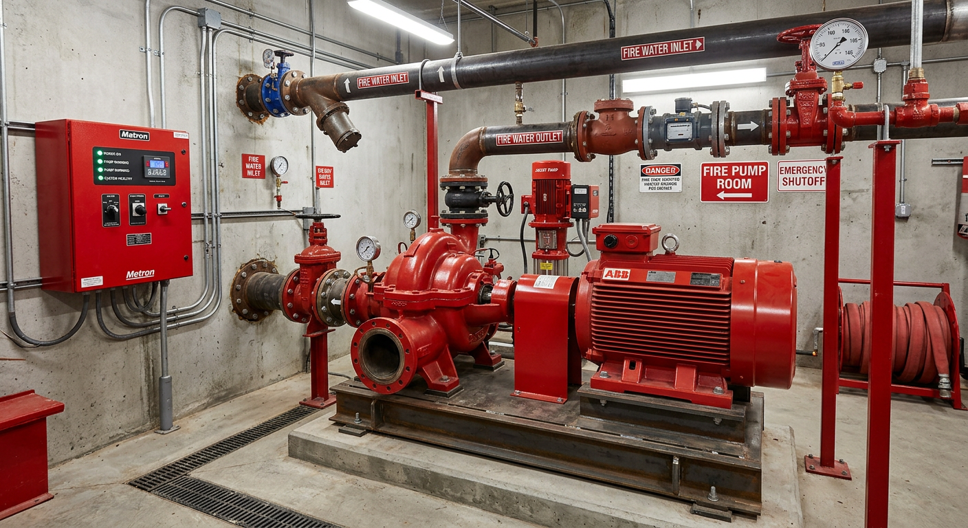
Fire pumps are the heart of a fire protection water supply where municipal pressure is insufficient. When a building is too tall, too large, or too remote for the city main to deliver the required flow and pressure at the most remote sprinkler or standpipe connection, a fire pump bridges the gap.
But a fire pump is not a commodity. It must be sized correctly — matching the system demand within NFPA 20’s allowable range. It must be selected for the specific application — horizontal split-case for high capacity, vertical inline for tight spaces, vertical turbine for suction lift. It must be driven by a reliable power source — electric motor where power is dependable, diesel engine where it is not. And it must be tested and maintained to ensure it starts when needed and performs at its rated curve.
This guide covers the design, selection, and testing requirements for fire pumps under NFPA 20, with a focus on the decisions that determine whether the system works when it matters.
◆ Section 1: When a Fire Pump Is Required
A fire pump is required when the available water supply cannot meet the system demand at the required pressure. The decision is driven by hydraulic calculation, not by a code threshold.
A. The Hydraulic Basis
The fire pump must be sized to provide the required flow and pressure at the most remote sprinkler or standpipe connection. If the city main cannot deliver that, a pump is needed.
B. Typical Triggers
| Condition | Why a Pump Is Needed |
|---|---|
| High-rise buildings | Municipal pressure insufficient at upper floors |
| Large footprint buildings | Friction loss through long piping runs |
| Remote water supplies | Distance from source reduces pressure |
| Insufficient municipal pressure | City main below system demand |
| Standpipe demand | 100 psi required at most remote hose connection (NFPA 14) |
Key point: The fire pump is not a substitute for adequate water supply—it is a supplement. If the water supply itself is inadequate, no pump will fix it.
Key Article: Article 111 — Standpipe and Hose System Design (NFPA 14)
Pro Tip: The decision to install a fire pump should be made during the hydraulic analysis, not after. If the calculation shows a deficit, the pump size and location should be determined before the building design is locked.
◆ Section 2: Pump Types and Characteristics
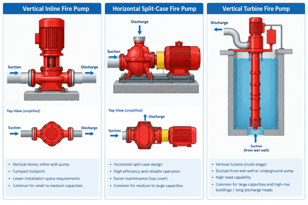
NFPA 20 recognizes three primary pump designs, each suited to different applications.
A. Vertical Inline Pumps
Vertical inline pumps are close-coupled with the motor mounted vertically above a horizontally aligned suction and discharge. They can be mounted directly to the floor without a concrete base. Because of this design, they need up to 30% less space than end-suction pumps of similar capacity, making them ideal for limited floor space, especially retrofits. A common product class tops out at about 1,000 GPM at 184 psi; NFPA 20 does not itself cap vertical inline pumps at that figure.
Applications: Limited space; light to medium capacity; retrofits.
B. Horizontal Split-Case Pumps
Horizontal split-case pumps are generally favored for larger commercial and industrial applications because of their high-capacity ranges. These floor-mounted pumps can be configured for clockwise or counterclockwise rotation. The upper half of the casing can be removed for servicing without disturbing the piping. They can handle capacities up to 5,000 GPM.
Applications: High capacity; large buildings; industrial facilities.
C. Vertical Turbine Pumps
If a building’s water source is below ground level (e.g., a reservoir, lake, or well), a vertical turbine fire pump is required. These pumps have a motor located above ground and coupled with a shaft and impeller assembly that is submerged into the water source. Their flow and head capacities are similar to horizontal split-case pumps.
Applications: Suction lift; below-grade water sources; municipal systems.
Key point: For new installations, NFPA 20 no longer allows the use of horizontal centrifugal fire pumps taking suction under lift (e.g., from a pond, reservoir, lake). If the water supply is such that suction lift cannot be avoided, a vertical-shaft turbine fire pump should be installed.
Pro Tip: The pump type is determined by the water source. If the source is below the pump, you need a vertical turbine. If the source is pressurized (city main or tank at grade), you can use a horizontal or vertical inline pump.
◆ Section 3: Sizing — Flow and Pressure
Fire pump sizing is governed by the relationship between the pump’s rated capacity and the system demand.
A. The 90%–140% Rule
NFPA 20 permits the demand for a suppression system to be between 90% and 140% of a fire pump’s rated capacity (NFPA 20-2019 4.10.1 and Annex A.4.10.1). The pressure demand must always be less than the pressure supplied by the pump’s performance curve along this range.
Example: A 750 gpm pump could supply a 1,000 gpm standpipe demand (133% of rated flow). The demand is between 90% and 140% of the rated flow.
B. Pump Performance Characteristics
Fire pumps are designed to provide their rated capacity with a built-in safety factor: 150 percent of rated capacity at 65 percent of rated pressure. This provides a cushion in the event of greater than expected demand.
| Characteristic | Requirement |
|---|---|
| Rated capacity | The pump’s nameplate flow rating (e.g., 1,000 gpm) |
| 150% overload | Pump must flow 150% of rated capacity at not less than 65% of total rated head |
| Churn (shutoff) pressure | The pressure at zero flow; typically falls between 101% and 140% of rated pressure |
C. Nameplate Horsepower
The horsepower on the nameplate in accordance with NFPA 20 4.11.3 is the same as the maximum brake horsepower required by 4.7.6. The driver shall be selected to provide the required power to operate the pump at rated speed and maximum pump load under any flow condition.
Key point: The pump must be sized so the system demand falls within the 90%–140% range. A demand below 90% of rated capacity means the pump is oversized. A demand above 140% means the pump is undersized.
Pro Tip: Always verify the pump curve against the system demand. A pump that meets the rated flow but falls below the required pressure at that flow is non-compliant.
◆ Section 4: Driver Types
NFPA 20 recognizes three acceptable driver types: electric motors, diesel engines, and steam turbines. Natural gas, LP gas, or gasoline engines are not recognized by NFPA 20.
A. Electric Motors
Electric motors are the most common driver type where a reliable power source is available. They are economical and require less maintenance than diesel engines.
Power requirements: A back-up power source, such as a dual utility power source or emergency generator, must be provided for electric fire pumps used in critical applications.
B. Diesel Engines
Diesel engines are often used when the electrical supply to the property is unreliable or has insufficient capacity. They are also used for redundant systems due to seismic zone or building height.
Derating requirements: Diesel engines must be derated for ambient conditions above baseline (77°F at 300-foot elevation). The nameplate rated horsepower is reduced by:
-
1 percent for every 10°F above 77°F
-
3 percent for every 1,000 feet above 300-foot elevation
Fuel requirements: The supply tank shall be located so the fuel supply pipe connection to the engine is no lower than the level of the engine fuel transfer pump. Engine manufacturer’s fuel pump static head pressure limits shall not be exceeded.
C. Steam Turbines
Steam turbines are infrequently utilized but remain an acceptable driver type under NFPA 20.
Key point: The driver must be listed for fire pump service and capable of providing the required power at rated speed and maximum pump load under any flow condition.
Pro Tip: For diesel engines, verify the derating calculation for your specific site conditions. A diesel engine rated at 500 HP at sea level may only deliver 450 HP at 2,000 feet elevation and 100°F ambient.
◆ Section 5: Controllers and Power Supply
Fire pump controllers are the interface between the driver and the system. They must be listed for fire pump service and installed per NFPA 20 and NFPA 70.
A. Controller Requirements
| Requirement | Specification |
|---|---|
| Listing | UL 218 listed |
| Assembly | Completely assembled, wired, and tested by the manufacturer before shipment |
| Enclosure | NEMA 250 Type 2 minimum for indoor controllers |
| Location | Within sight of the driver |
B. Remote Alarm Panel
NFPA 20 requires a remote alarm panel located in an area that is constantly attended if the fire-pump controller is in a location that is not constantly attended or supervised.
Alarms and status indications include:
-
Supervised power on
-
Controller connected to alternate power source
-
Controller main switch turned to off or manual position
-
Common pump room trouble
C. Low-Suction-Shutdown Panels
Although prohibited by NFPA 20, some local laws or AHJs mandate the use of low-suction-shutdown panels to inhibit starting and activate shutdown of automatically controlled fire pumps on low-suction pressure.
Key point: The controller must be listed and installed per NFPA 20. Field modifications or non-listed controllers are violations.
Pro Tip: Verify the remote alarm panel location with the building owner or facility manager. It must be in a constantly attended area to serve its purpose.
◆ Section 6: Fire Pump Room Requirements
The fire pump room must meet specific requirements for location, protection, and environment.
A. Location
The fire pump room generally should be located at or near an exterior wall, nearest to the point of connection. The location is a critical component of the building’s life safety design and should be reviewed and approved by the fire department before site permit approval.
B. Protection — NFPA 20 4.14.1.3
The fire pump room protection requirements depend on the driver type.
| Driver Type | Sprinkler Requirement |
|---|---|
| Diesel engine pump drivers with day tanks | Automatic sprinkler system required — installed per NFPA 13 as an Extra Hazard Group 2 occupancy (NFPA 20 4.14.1.3) |
| Electric-only pump rooms | Not independently required to be sprinklered under NFPA 20. If the building is sprinklered throughout, the pump room is covered as part of the building system. |
Key point: The diesel-room requirement for Extra Hazard Group 2 classification is long-standing in NFPA 20 — it appears in the 2016, 2019, and 2022 editions, not as a new 2025 addition.
Note on edition numbering: The section number for this requirement has varied between editions — 4.13.1.3 in some editions, 4.14.1.3 in others. Verify the exact section against your AHJ-adopted edition.
C. Environment
The temperature inside the fire pump room shall be maintained above 40°F for protection against freezing and below 90°F for protection against overheating of control elements.
Key point: The fire pump room is not a utility closet. It requires heating, ventilation, drainage, and — for diesel rooms — sprinkler protection.
Pro Tip: For new construction, confirm which NFPA 20 edition your AHJ has adopted and verify the diesel-room sprinkler requirement against the actual text of the applicable section.
◆ Section 7: Acceptance Testing
Acceptance testing verifies that the installed pump meets its rated performance and that all components function correctly.
A. When Acceptance Testing Is Required
An acceptance test is required whenever a component in a fire pump is adjusted, repaired, rebuilt, or replaced. The tests required to restore the system to service shall be performed in accordance with NFPA 25 Table 8.6.1.
Controller replacement: A full acceptance test is required when a fire pump controller is replaced. The controller must be UL-listed and FM-approved.
B. Test Requirements
| Requirement | Specification |
|---|---|
| Field acceptance criterion | Installed pump must match its own certified shop curve within the accuracy limits of the test equipment (NFPA 20 14.2.4) |
| Test equipment accuracy | ±1% (equipment accuracy, not field tolerance) |
| Voltage | +10% to -5% for the driver |
| Pressure variance | ±5% for pressure recording (NFPA 25 8.3.2.1.2.1) |
Important distinction: The ±1% figure is the accuracy of the test equipment, not the field acceptance tolerance. The field acceptance criterion is that the installed pump’s performance matches its certified shop curve within the accuracy of the test instrumentation.
C. Test Data
Complete pump acceptance test data shall be recorded on forms that give the detail pump information such as that indicated in Figure A-11-2.6.3(f) of NFPA 20. All test data records shall be submitted in a three-ring binder.
Key point: Acceptance testing is not a formality. It verifies that the pump, driver, controller, and piping work together as a system.
Pro Tip: It takes two people approximately four hours to conduct a typical fire pump acceptance test (from setup to cleanup). Plan accordingly.
◆ Section 8: Periodic Testing and Maintenance (NFPA 25)
Once installed, the fire pump must be inspected, tested, and maintained per NFPA 25.
A. ITM Intervals (NFPA 25 2026 Edition)
| Interval | Activity |
|---|---|
| Weekly | Electric pump system — run pump |
| Monthly | Diesel engine system — run pump; check fuel, oil, coolant |
| Annually | Pump performance (flow) test — 8.3.3.1 |
| Annually | Flow meters — 8.3.3.5.3 |
| Annually | Main pressure relief valve — 8.3.3.12 |
| 5 Years | Power transmission components with elastomeric materials — 8.1.1.2.24 |
B. Diesel Engine ITM
| Interval | Activity |
|---|---|
| Weekly | Check fuel tank for water/foreign materials |
| Annually | Diesel fuel testing — 8.3.4.1 |
| Annually | Engine lubricating oil (or 50 operating hours) |
C. Performance Criteria
NFPA 25 8.3.7.3 and 8.3.7.4 outline what is considered acceptable. If a pump yields results less than 95% of the pump’s rated flow and pressure, an investigation must be conducted as to why the pump is yielding degraded performance.
Key point: The weekly churn run is not optional. It verifies that the pump starts and runs, and it exercises the controller and driver.
Pro Tip: Keep records. NFPA 25 requires documentation of all ITM activities, and the AHJ will ask for them during inspections.
◆ Section 9: Design Checklist for Fire Pump Systems
| Item | Status | Notes |
|---|---|---|
| Hydraulic calculation complete | ☐ | Demand within 90%–140% of rated capacity |
| Pump type selected | ☐ | Horizontal split-case, vertical inline, or vertical turbine |
| Driver type selected | ☐ | Electric, diesel, or steam |
| Diesel derating calculated | ☐ | 1% per 10°F above 77°F; 3% per 1,000 ft above 300 ft |
| Controller listed and installed | ☐ | UL 218; within sight of driver |
| Remote alarm panel | ☐ | In constantly attended area if controller location is not attended |
| Fire pump room location | ☐ | At/near exterior wall; reviewed by fire department |
| Diesel room sprinklered | ☐ | Required per NFPA 20 4.14.1.3; Extra Hazard Group 2 |
| Electric room sprinklered | ☐ | Only if building sprinklered throughout |
| Room temperature | ☐ | 40°F–90°F |
| Acceptance test performed | ☐ | Per NFPA 20 14.2.4; controller replacement triggers full test |
| Acceptance test data recorded | ☐ | Figure A-11-2.6.3(f) format; three-ring binder |
| Weekly churn run | ☐ | Electric and diesel |
| Annual flow test | ☐ | NFPA 25 8.3.3.1 |
| Diesel fuel testing | ☐ | Annually |
| Records maintained | ☐ | All ITM activities documented |
◆ Section 10: Common Mistakes and How to Avoid Them
| Mistake | Why It’s a Problem | How to Fix |
|---|---|---|
| Demand outside 90%–140% range | Pump oversized or undersized | Verify demand against pump curve |
| Diesel engine not derated for altitude/temperature | Insufficient power at site conditions | Calculate derating; select correct engine |
| Non-listed controller | Violates NFPA 20; may not function | Use UL 218 listed controller |
| Remote alarm panel not in attended area | Alarms not monitored | Verify panel location |
| Assuming all fire pump rooms require sprinklers | Over-design; incorrect scope | Verify NFPA 20 4.14.1.3 — applies to diesel rooms |
| Omitting sprinklers in diesel room | Violates NFPA 20; Extra Hazard Group 2 required | Install per NFPA 13 as Extra Hazard Group 2 |
| Acceptance test not performed after controller replacement | Non-compliant; system may not function | Full acceptance test required |
| Weekly churn run skipped | Pump may not start when needed | Perform weekly; document |
| Performance below 95% of rated | Degraded pump; investigation required | Conduct investigation; repair or replace |
| Churn pressure outside 101%–140% range | System component overpressure or inadequate performance | Verify relief valve setting and pump curve |
◆ Section 11: Conclusion
Fire pump design is a discipline of hydraulics, power, and reliability. The pump must be sized to meet the system demand within the 90%–140% range. It must be selected for the water source and space constraints. It must be driven by a reliable power source — electric where power is dependable, diesel where it is not. And it must be tested and maintained to ensure it starts when needed and performs at its rated curve.
Key Takeaways:
-
Fire pumps supplement, not replace, the water supply — they bridge the gap between available pressure and system demand.
-
Pump types differ by application — vertical inline for space, horizontal split-case for capacity, vertical turbine for suction lift.
-
Demand must be 90%–140% of rated capacity (NFPA 20 4.10.1).
-
Pumps must deliver 150% of rated capacity at 65% of rated head; churn pressure typically falls between 101% and 140% of rated pressure.
-
Electric motors, diesel engines, and steam turbines are the only acceptable drivers; gasoline is not recognized.
-
Diesel engines must be derated for altitude and temperature.
-
Controllers must be UL 218 listed and installed within sight of the driver.
-
Diesel pump rooms require automatic sprinklers as an Extra Hazard Group 2 occupancy per NFPA 20 4.14.1.3 — this requirement is long-standing, not new to the 2025 edition.
-
Electric-only pump rooms are not independently required to be sprinklered under NFPA 20.
-
Field acceptance testing verifies the installed pump matches its certified shop curve within test equipment accuracy (NFPA 20 14.2.4).
-
NFPA 25 ITM is mandatory — weekly churn runs, annual flow tests, and documented records.
Take Action Today:
-
Verify the hydraulic calculation places demand within 90%–140% of rated capacity.
-
Confirm pump type matches the water source and space constraints.
-
Verify driver type and derating for site conditions.
-
Confirm controller listing and location.
-
Verify remote alarm panel location.
-
Confirm diesel room sprinkler requirements per NFPA 20 4.14.1.3.
-
Verify acceptance test documentation is complete.
-
Confirm weekly churn runs and annual flow tests are performed and documented.
-
Investigate any performance below 95% of rated flow or pressure.
-
Maintain all ITM records for AHJ review.
Continue Reading from Our Series:
-
Related guide: Standpipe and Hose System Design (NFPA 14) (Article 111)
-
Learn more: Commercial Building Code Requirements for Fire Sprinkler Systems (Article 23)
-
Read more: How to Design for Fire Safety in High-Rise Buildings (Article 77)