IMPORTANT DISCLAIMER: This guide references NFPA 14, Standard for the Installation of Standpipe and Hose Systems; NFPA 25, Standard for the Inspection, Testing, and Maintenance of Water-Based Fire Protection Systems; NFPA 13, Standard for the Installation of Sprinkler Systems; NFPA 20, Standard for the Installation of Stationary Pumps for Fire Protection; NFPA 72, National Fire Alarm and Signaling Code; NFPA 101, Life Safety Code; and the International Fire Code (IFC). These codes vary significantly by edition and are frequently amended by state and local jurisdictions. NFPA 14 editions include 2019 and 2024, with a 2027 edition in development. The most recent published edition is NFPA 14 (2024), but AHJ-adopted editions commonly lag behind by one or more cycles. The 2027 edition is developing new requirements for pressure-reducing hose valve selection and acceptance testing. Local amendments and the edition adopted by your Authority Having Jurisdiction (AHJ) always control. This guide is a starting point only—always verify the specific requirements applicable to your project with your local AHJ.
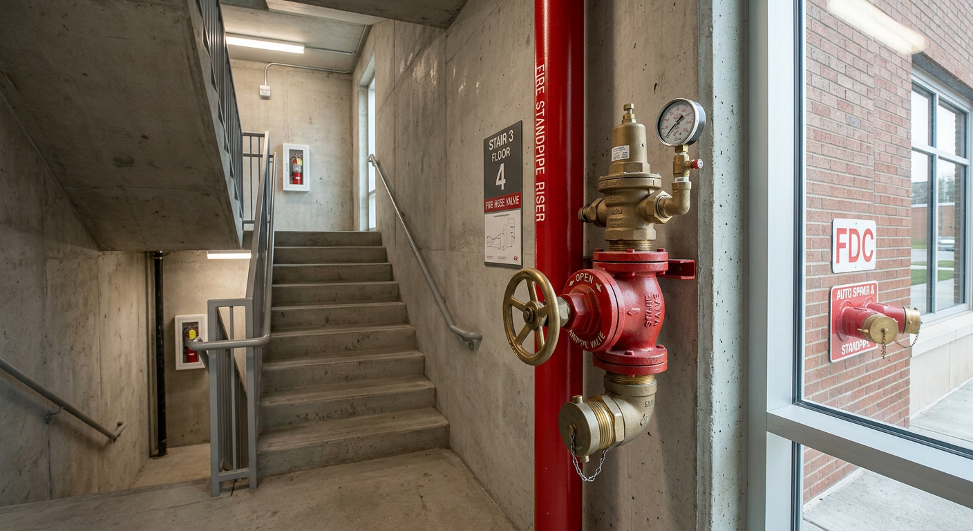
Standpipe systems are the backbone of manual firefighting in buildings too tall or too large for fire department hose lays from the street. When firefighters arrive at a high-rise fire, they do not stretch hose from the engine to the 15th floor. They connect to the fire department connection, charge the system, and advance hose from the standpipe hose valve on the fire floor.
That operational reality drives every design decision in NFPA 14. The standpipe must deliver 100 psi at the most remote hose connection while flowing the required system demand. It must be accessible from the stairwell. It must be protected from fire. And in buildings where static pressures exceed 175 psi, it must regulate those pressures to protect both equipment and firefighters.
This guide covers the design requirements for standpipe systems under NFPA 14, with a focus on the decisions that drive layout, hydraulics, and pressure control.
◆ Section 1: Standpipe Classes and Types
NFPA 14 classifies standpipe systems by their intended use and type of water supply.
A. Standpipe Classes
| Class | Intended Use | Hose Connection Size | Water Supply |
|---|---|---|---|
| Class I | Fire department personnel | 2½-inch (65 mm) | 500 gpm minimum |
| Class II | Building occupants | 1½-inch (38 mm) | 100 gpm minimum |
| Class III | Both fire department and occupants | 2½-inch and 1½-inch | 500 gpm minimum |
Class I systems are for trained firefighting personnel and supply effective fire streams during more advanced fire stages. Class II systems are for untrained building occupants and use 1½-inch hose connections. Class III systems combine both features and must allow for simultaneous use of Class I and Class II services.
Key point: The class designation determines the minimum flow requirement. Class I and Class III systems require 500 gpm from the hydraulically most remote standpipe.
B. Standpipe Types
NFPA 14 identifies five types of standpipes based on water supply and activation:
| Type | Description | Water Supply |
|---|---|---|
| Automatic-Wet | Filled with water at all times; connected to permanent water supply meeting flow/pressure | Permanent, adequate |
| Manual-Wet | Filled with water at all times; water supply not adequate for flow/pressure | Requires fire department pumper |
| Automatic-Dry | Filled with pressurized air; dry pipe valve admits water automatically | Permanent, adequate |
| Semi-Automatic-Dry | Empty pipe; deluge valve admits water upon remote activation at hose connection | Permanent, adequate |
| Manual-Dry | Empty pipe; not connected to water supply | Requires fire department pumper |
Key point: Manual standpipe systems require water from a fire department pumper to meet flow and pressure requirements. They must have an approved water supply accessible to a fire department pumper.
Pro Tip: Where a manual standpipe is provided, each hose connection must have a conspicuous sign reading “Manual Standpipe for Fire Department Use Only”.
◆ Section 2: When Standpipes Are Required
The IFC and NFPA 101 establish the triggers for standpipe installation. NFPA 14 does not itself mandate where standpipes are required—it governs their design once required.
A. IFC Triggers
The IFC requires standpipes under the following conditions:
| Trigger | Threshold |
|---|---|
| Stories above or below grade | Four or more stories |
| Building height | Floor level of highest story more than 30 feet above lowest level of fire department access |
| Building depth | Floor level of lowest story more than 30 feet below highest level of fire department access |
B. Existing Buildings
Existing structures not complying with the IBC with occupied floors located more than 50 feet above or below the lowest level of fire department access must be equipped with standpipes.
Key point: The standpipe requirement is triggered by building height or depth—not by occupancy type. A four-story office building requires standpipes. So does a building where the highest occupied floor is more than 30 feet above fire department access.
Pro Tip: Verify the exact trigger against your AHJ-adopted IFC or NFPA 101 edition. The thresholds have remained consistent, but local amendments may modify them.
◆ Section 3: Hydraulic Design Requirements
The hydraulic design of a standpipe system determines whether it can deliver the required flow and pressure at the most remote hose connection.
A. Minimum Flow and Pressure
| Requirement | Specification |
|---|---|
| Minimum pressure at most remote 2½-inch hose connection | 100 psi |
| Class I/III minimum flow | 500 gpm |
| Additional standpipes | 250 gpm each |
| Maximum total flow — sprinklered throughout | 1,000 gpm |
| Maximum total flow — not sprinklered throughout | 1,250 gpm |
| Duration (NFPA 14 standpipe minimum) | 30 minutes — flat minimum for Class I, II, and III standpipe systems |
Note on duration: NFPA 14 sets a flat 30-minute minimum water supply duration for standpipe systems, regardless of hazard classification. In combined sprinkler/standpipe systems, the water supply must also satisfy the NFPA 13 sprinkler demand, which has hazard-based duration requirements (e.g., 60–90 minutes for Ordinary Hazard). Verify the combined demand against both standards.
Key point: The total flow cap depends on whether the building is sprinklered throughout. A system in a non-sprinklered building may need to flow up to 1,250 gpm—250 gpm more than a sprinklered building with the same standpipe configuration.
B. Hydraulic Calculation Method
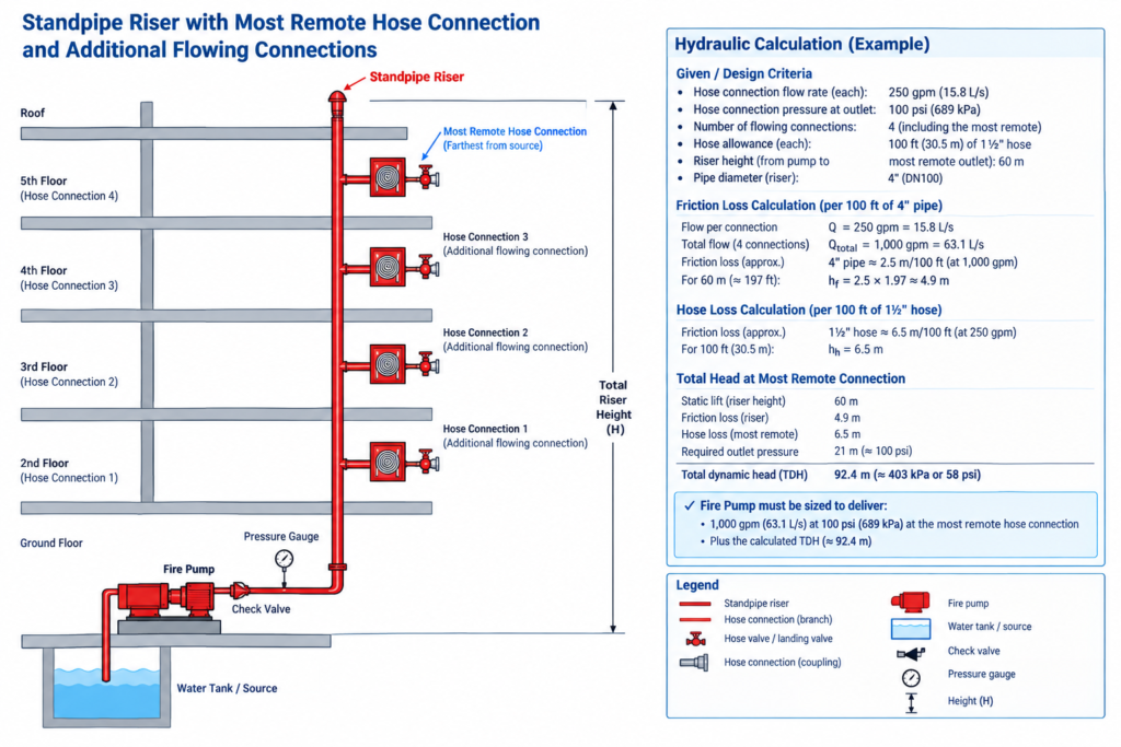
The hydraulically most demanding hose valve must flow 250 gpm at 100 psi. Additional hose valves are then flowed at 250 gpm each until the total flow requirement is met.
Important: For horizontal standpipes, NFPA 14 requires calculating three hose valves instead of two. A horizontal standpipe is defined as horizontal piping that supplies two or more hose connections on a floor.
Key Article: Article 77 — How to Design for Fire Safety in High-Rise Buildings
Pro Tip: The hydraulic calculation must demonstrate that the system can deliver 100 psi at the most remote hose connection while flowing the required total gpm. A system that meets the flow requirement but fails the pressure requirement is non-compliant.
◆ Section 4: Pressure Regulation
Pressure regulation is one of the most technically challenging aspects of standpipe design. In high-rise buildings, the pressure required to deliver 100 psi at the top of the system can exceed 175 psi at lower floors.
A. When Pressure Regulation Is Required
NFPA 14 requires pressure-regulating devices where:
| Condition | Requirement |
|---|---|
| Static pressure at 2½-inch hose connection exceeds 175 psi | Pressure-regulating device required to limit static and residual pressures to 175 psi |
| Residual pressure at 1½-inch hose connection exceeds 100 psi | Pressure-restricting device required to limit residual pressure to 100 psi |
| Static pressure at 1½-inch hose connection exceeds 175 psi | Pressure-regulating device required to limit static and residual to 100 psi |
B. Types of Pressure-Regulating Devices
| Device | Function | Application |
|---|---|---|
| Pressure-Reducing Valve (PRV) | Reduces downstream pressure under both flow and no-flow conditions | Where static pressure exceeds 175 psi |
| Pressure-Restricting Device | Reduces downstream pressure under flow conditions only | Where pressure does not exceed 175 psi but needs restriction |
| Pressure-Reducing Valve Assembly (PRVA) | Two PRVs in series for redundancy | Where serving more than two hose valves |
Key point: PRVs are designed to reduce pressure under both static (no flow) and residual (flowing) conditions. Pressure-restricting devices only work under flow conditions.
C. PRV Selection Challenges
The 2027 NFPA 14 second draft addresses a longstanding design gap: PRVs must be selected for the full range of operating conditions, not just full system demand. The committee identified three critical flow conditions for evaluation:
-
No flow (static condition)
-
Single hose valve flow (250 gpm from most remote valve)
-
Full standpipe system demand
A valve that appears acceptable during full demand may fall outside its approved operating range during low-flow conditions where inlet pressures rise.
Pro Tip: PRV selection cannot be based on a single hydraulic calculation. The designer must calculate available inlet pressures at each PRV location under multiple flow conditions and use manufacturer’s valve data to select the appropriate valve and setting.
◆ Section 5: Hose Connections and Valves
Hose connection location and accessibility determine whether firefighters can effectively use the standpipe.
A. Location Requirements
| Requirement | Specification |
|---|---|
| Height | 3 feet to 5 feet above floor; measured to center of valve; recommended 42 inches |
| Clearance | Handle must have 3 inches clearance from adjacent objects |
| Obstruction | Shall not be obstructed by doors, walls, or storage |
| Horizontal exits | Visible and within 20 feet of each side of the exit |
| Travel distance (NFPA 14) | 130 feet (non-sprinklered); 200 feet (sprinklered) |
| Travel distance (IFC trigger) | Additional hose connections required where travel exceeds 150 feet in non-sprinklered buildings |
Important distinction: NFPA 14 limits travel distance to 130 feet in non-sprinklered buildings and 200 feet in sprinklered buildings. The IFC uses a 150-foot trigger for requiring additional hose connections. Both apply—the IFC trigger determines when more connections are required; NFPA 14 limits the maximum distance from any point to a connection.
B. Valve Requirements
Each standpipe shall be equipped with approved outlet valves that discharge horizontally. The valve height requirement is measured to the centerline of the valve.
2024 NFPA 14 clarifications: The 2024 edition added requirements that hose connections on horizontal exits be visible and within 20 feet of each side, prohibited obstruction by doors, and required hose connections on occupiable landscaped roofs.
Key point: The hose connection is where the firefighter connects the attack hose. If it is hidden behind a door, installed too high, or obstructed by storage, the system fails at the point of use.
Pro Tip: Walk to every hose connection in your building. Open the cabinet. Can you reach the valve? Is there clearance for a gloved hand? If not, it is a violation.
◆ Section 6: Fire Department Connection
The fire department connection (FDC) is the point where the fire department supplements the standpipe water supply.
A. Location Requirements
| Requirement | Specification |
|---|---|
| Height | 18 inches to 48 inches above adjoining ground |
| Distance from hydrant | Within 100 feet of a low-pressure fire hydrant |
| Access | Approved location; not obstructed |
B. Threads and Connections
FDC and outlet valves typically use 2½-inch National Standard hose threads (NH/NST). Some jurisdictions require 3-inch connections—verify with your AHJ. Thread size is one of the most locally varied items in standpipe design.
C. Signage and Identification
The FDC pipe color coding—where adopted as a local convention—uses the following convention:
| Color | System Served |
|---|---|
| Green | Fire sprinkler system exclusively |
| Red | Standpipe system exclusively |
| Yellow | Combination sprinkler/standpipe system |
Note: This color convention is not an NFPA 14 requirement. It is a local/AHJ convention (e.g., New York City). Verify the applicable convention in your jurisdiction.
Key point: The FDC must be accessible and unobstructed. Firefighters arriving at a high-rise fire connect to the FDC first—if it is blocked by parked cars or landscaping, the system cannot be charged.
Pro Tip: Verify FDC location, thread size, and color coding with your fire department during pre-incident planning. They know what they need.
◆ Section 7: Pipe Sizing and Protection
A. Minimum Pipe Sizes
| System | Minimum Size |
|---|---|
| Class I and III standpipes | 4 inches |
| Combined system | 6 inches; 4 inches if fully sprinklered and hydraulically calculated |
| Branch lines | 2½ inches minimum; sized hydraulically |
B. Pipe Protection
Standpipes and lateral piping supplied by standpipes must be located in enclosed exit stairs or protected to the same degree as stairs. In buildings equipped throughout with automatic sprinklers, laterals not within enclosed stairs are not required to be enclosed in fire-resistance-rated construction.
C. Interconnection
Where two or more standpipes are installed, they must be interconnected.
Pro Tip: The standpipe must survive the fire it is designed to fight. If the piping runs through a fire area without protection, it may fail before firefighters can use it.
◆ Section 8: High-Rise and Large-Area Challenges
Standpipe design in high-rise buildings faces unique challenges.
A. Maximum System Pressure
NFPA 14-2019 increased the maximum permitted system pressure from 350 psi to 400 psi. Verify against your AHJ-adopted edition.
B. Scissor Stairs
Where scissor stairs are provided, separate standpipes shall be provided for each stair. The system may need to flow 750 gpm (500 gpm for the first standpipe plus 250 gpm for the second).
C. Horizontal Standpipes
A horizontal standpipe supplies two or more hose connections on a floor. Horizontal standpipes must be minimum 4 inches and require an isolation valve. When a horizontal standpipe supplies three or more hose valves, the hydraulic calculation must flow 750 gpm through that standpipe.
Key Article: Article 77 — How to Design for Fire Safety in High-Rise Buildings
Pro Tip: In high-rise buildings, the PRV station approach (a PRVA serving multiple hose valves) is often more advantageous than individual floor-level PRVs. Evaluate both options.
◆ Section 9: Design Checklist for Standpipe Systems
| Item | Status | Notes |
|---|---|---|
| Standpipe required? | ☐ | IFC: 4+ stories or >30 ft above/below fire access |
| Class determined | ☐ | Class I, II, or III |
| Type determined | ☐ | Automatic-wet, manual-wet, automatic-dry, semi-automatic-dry, manual-dry |
| Hydraulic calculation complete | ☐ | 100 psi at most remote; 500 gpm minimum |
| Total flow cap verified | ☐ | 1,000 gpm (sprinklered) / 1,250 gpm (non-sprinklered) |
| Duration verified | ☐ | 30 min (NFPA 14); combined systems also meet NFPA 13 |
| Horizontal standpipe calculation | ☐ | 3 hose valves if applicable; 750 gpm if 3+ valves |
| Pressure regulation evaluated | ☐ | PRV if static >175 psi; pressure-restricting if residual >100 psi |
| PRV selection verified | ☐ | Multiple flow conditions; manufacturer data |
| Hose connection height | ☐ | 3–5 ft above floor; center of valve |
| Hose connection clearance | ☐ | 3 inches for handle; unobstructed |
| Travel distance | ☐ | 130 ft (non-sprinklered); 200 ft (sprinklered) per NFPA 14 |
| FDC location | ☐ | 18–48 inches above ground; within 100 ft of hydrant |
| FDC thread size | ☐ | Typically 2½-inch NH/NST; verify AHJ |
| Pipe sizing | ☐ | 4-inch Class I/III minimum |
| Pipe protection | ☐ | Enclosed stairs or fire-rated protection |
| Interconnection | ☐ | Multiple standpipes interconnected |
| Manual standpipe signage | ☐ | “Manual Standpipe for Fire Department Use Only” |
| Acceptance testing | ☐ | Hydrostatic at 200 psi or 50 psi over max operating, 2 hours |
| Periodic testing | ☐ | Flow test every 5 years on automatic standpipes |
| Maximum system pressure | ☐ | 400 psi per NFPA 14-2019 |
◆ Section 10: Common Mistakes and How to Avoid Them
| Mistake | Why It’s a Problem | How to Fix |
|---|---|---|
| Insufficient pressure at remote hose connection | Firefighters cannot effectively attack fire | Verify 100 psi minimum; adjust pump or pipe sizing |
| Underestimating total flow for non-sprinklered building | System under-designed by 250 gpm | Verify 1,250 gpm cap for non-sprinklered buildings |
| Applying NFPA 13 duration to standpipe-only system | Over-designs the standpipe water supply | Use 30-min NFPA 14 minimum for standpipe-only; combined systems meet both |
| PRV not selected for low-flow conditions | Valve fails to regulate during single-hose operation | Calculate inlet pressures under multiple flow conditions |
| Hose connection obstructed by door or storage | System unusable at point of need | Verify 3-inch handle clearance; maintain access |
| FDC blocked by parking or landscaping | System cannot be charged | Verify FDC location with fire department |
| Manual standpipe without signage | Firefighters may not know it requires pumper supply | Install required signage |
| Horizontal standpipe undersized | Cannot meet 750 gpm demand | Verify 4-inch minimum and hydraulic calculation |
| No pressure regulation where required | Equipment damage or firefighter injury | Install PRV where static exceeds 175 psi |
| Scissor stairs with single standpipe | Non-compliant; insufficient flow | Provide separate standpipe per stair |
| Using wrong maximum pressure (350 psi) | Under-designed system | Verify 400 psi per NFPA 14-2019 |
◆ Section 11: Conclusion
Standpipe system design is a discipline of hydraulics, pressure, and access. The system must deliver 100 psi at the most remote hose connection while flowing the required demand. It must be accessible from the stairwell. It must regulate pressure where static pressures exceed 175 psi. And it must survive the fire it is designed to fight.
Key Takeaways:
-
Class I systems are for fire department use; Class II for occupants; Class III combines both.
-
Standpipes are required at four or more stories, or where the highest floor exceeds 30 feet above fire department access.
-
Minimum flow is 500 gpm for Class I/III, with 250 gpm for each additional standpipe.
-
Maximum total flow is 1,000 gpm (sprinklered) or 1,250 gpm (non-sprinklered) .
-
100 psi minimum at the most remote 2½-inch hose connection.
-
Duration is 30 minutes per NFPA 14 for standpipe systems; combined systems must also meet NFPA 13 sprinkler duration.
-
Travel distance to hose connections is 130 feet (non-sprinklered) or 200 feet (sprinklered) per NFPA 14.
-
Pressure regulation is required where static pressure exceeds 175 psi.
-
PRV selection must consider multiple flow conditions, not just full demand.
-
Hose connections must be 3–5 feet above floor with 3-inch handle clearance.
-
FDC must be 18–48 inches above ground and within 100 feet of a hydrant.
-
Maximum system pressure is 400 psi per NFPA 14-2019.
Take Action Today:
-
Verify standpipe class and type for your building.
-
Confirm hydraulic calculation demonstrates 100 psi at most remote connection.
-
Verify total flow cap for sprinklered vs. non-sprinklered construction.
-
Verify duration: 30 min for standpipe-only; combined systems meet NFPA 13.
-
Verify pressure regulation where static pressure exceeds 175 psi.
-
Check PRV selection for multiple flow conditions.
-
Walk to every hose connection: height, clearance, accessibility.
-
Verify travel distance to hose connections (130 ft / 200 ft).
-
Verify FDC location, thread size, and clearance with your fire department.
-
Confirm pipe sizing and protection.
-
Verify interconnection of multiple standpipes.
-
Confirm acceptance testing and periodic flow testing records.
Continue Reading from Our Series:
-
Related guide: How to Design for Fire Safety in High-Rise Buildings (Article 77)
-
Learn more: Commercial Building Code Requirements for Fire Sprinkler Systems (Article 23)
-
Read more: Fire Safety for Marinas, Piers, and Waterfront Structures (Article 110)