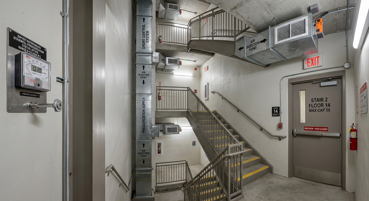
IMPORTANT DISCLAIMER: This guide references NFPA 92, Standard for Smoke Control Systems (2024 edition); the International Building Code (IBC), Section 909 (Smoke Control Systems), Section 403 (High-Rise Buildings), Section 909.20 (Smokeproof Enclosures), Section 1023.11 (Smokeproof Enclosures), Section 909.11 (Standby Power), and Section 1705.18 (Special Inspection for Smoke Control); NFPA 101, Life Safety Code (Section 9.3 on Smoke Control Systems and Section 7.2.1.4.5 on Door Forces); and ASHRAE/SFPE Principles of Smoke Management. These codes vary significantly by edition and are frequently amended by state and local jurisdictions. NFPA 92 editions include 2012, 2015, 2018, 2021, and 2024. The most recent published edition is NFPA 92 (2024), but AHJ-adopted editions commonly lag behind by one or more cycles. IBC Section 909 and NFPA 92 requirements have evolved across editions — verify specific requirements against your AHJ-adopted edition. Older IBC editions used §1704.xx numbering for special inspection of smoke control. Local amendments and the edition adopted by your Authority Having Jurisdiction (AHJ) always control. This guide is a starting point only. Always verify the specific requirements applicable to your project with your local AHJ.
Stairwell pressurization is the primary means of keeping exit stairs tenable in high-rise buildings. It uses mechanical fans to maintain a positive pressure differential across the stair enclosure, preventing smoke infiltration when doors open for evacuation or firefighter access. Without pressurization, a stairwell can act as a chimney, drawing smoke from the fire floor and rendering the primary means of egress unusable.
The challenge is that stairwell pressurization is not simply a matter of “adding a fan.” The system must maintain adequate pressure when doors are closed, yet not create door opening forces that occupants cannot overcome. It must account for stack effect, wind, and the interaction with other building systems. And it must be tested under conditions that reflect real-world fire scenarios—not just a single commissioning test on a mild spring day.
This article covers the design approaches, pressure differentials, and testing requirements for stairwell pressurization under NFPA 92 and IBC 909.
◆ Section 1: Why Stair Pressurization Matters
Smoke is the primary killer in building fires. In high-rise buildings, the stack effect—the natural upward movement of air due to temperature differences between inside and outside—can drive smoke into stairwells at alarming speed. A pressurized stairwell reverses this flow, creating a positive pressure barrier that keeps smoke out.
| Factor | Challenge |
|---|---|
| Stack effect | Natural buoyancy drives smoke vertically through building shafts |
| Door openings | Evacuation and firefighter access open doors, dropping pressure |
| Door opening force | Excessive pressure makes doors difficult or impossible to open |
| System interaction | Stair and elevator pressurization can create competing pressures |
| Testing conditions | Commissioning under mild weather may not reflect winter/summer stack effect |
Key point: The objective of stairwell pressurization is to provide an acceptable environment within a stairwell in the event of a fire, furnishing an egress route for occupants and a staging area for firefighters.
Key Article: Article 117 — Smoke Control System Design and Testing (NFPA 92)
Pro Tip: NFPA 92 does not govern when a smoke control system is required. That comes from the building code or NFPA 101 occupancy chapters. For high-rise buildings, the driver is the smokeproof enclosure requirement for stairs serving floors more than 75 ft above the lowest level of fire department vehicle access (IBC §403.5.4, with §909.20 and §1023.11). Pressurization is one way to satisfy it. Note that the 75 ft is measured from fire department vehicle access, not from grade.
◆ Section 2: Regulatory Framework
Stair pressurization is governed by a coordinated set of codes and standards.
| Standard | Scope | Key Provisions |
|---|---|---|
| NFPA 92 (2024) | Design, installation, testing of smoke control systems | Pressure differentials, door forces, acceptance testing |
| NFPA 101 §9.3 | Life safety requirements for smoke control | References NFPA 92 |
| IBC §909 | Smoke control systems | Design requirements, activation, standby power |
| IBC §909.20.5 | Smokeproof enclosures — stair pressurization alternative | Minimum 0.15 in. w.c. (37 Pa); maximum 0.35 in. w.c. (87 Pa) |
| IBC §403.5.4 | High-rise buildings | Smokeproof enclosure requirement for stairs >75 ft |
| ASHRAE/SFPE | Principles of Smoke Management | Engineering design guidance |
Key point: NFPA 92 defines how the system must perform, with general smoke barrier pressure differentials. The IBC adds stair-specific requirements for the smokeproof enclosure alternative (IBC §909.20.5) that are separate and more stringent than the NFPA 92 barrier values.
Key Article: Article 77 — How to Design for Fire Safety in High-Rise Buildings
Pro Tip: Establish an understanding with the AHJ on expected performance and acceptance test procedures early in design. The absence of a consensus agreement historically creates problems at system acceptance, including delays in obtaining a certificate of occupancy.
◆ Section 3: Design Approaches
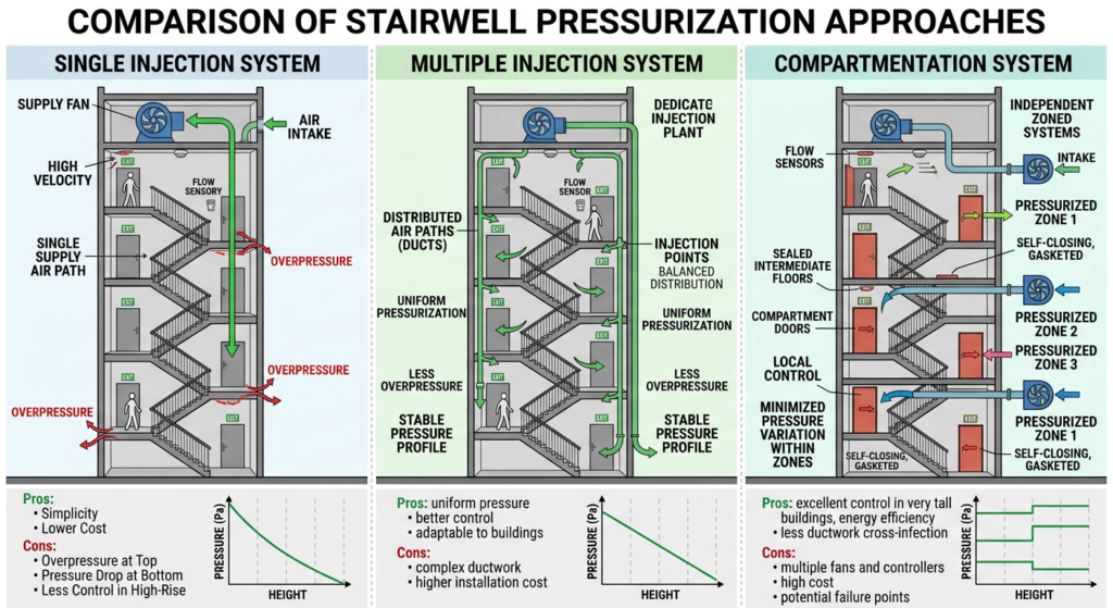
NFPA 92 and industry practice recognize several approaches to stairwell pressurization.
A. Single Injection
A single injection system supplies pressurization air to the stairwell at one location.
Limitation: For tall stairwells, single injection systems can fail when a few doors are open near the air supply injection point. This mode of failure is most likely for injection at the ground level when a ground floor door to the outside is open.
Recommendation: The injection point should not be at the same level as an exterior door. Some designers limit the height of top injection stairwells from eight to twelve stories.
B. Multiple Injection
For taller stairwells, multiple injection is recommended. Multiple supply injection points at a minimum of every three floors (unless design analysis can justify greater spacing) provide uniform pressurization.
C. Compartmentation
An alternative to multiple injection is compartmentation of the stairwell into sections, each with at least one supply air injection point.
Limitation: When doors between compartments are open, the effect of compartmentation is lost. It is inappropriate for densely populated buildings where total evacuation by stairwell is planned. It can be effective for very tall buildings when a staged evacuation plan is used.
| Approach | Best Application | Limitation |
|---|---|---|
| Single injection | Stairwells up to 8–12 stories | Fails when doors open near injection point |
| Multiple injection | Tall stairwells | More complex; requires more ductwork |
| Compartmentation | Very tall buildings with staged evacuation | Lost when doors between compartments open |
Key point: The design approach must account for the building’s evacuation strategy. Compartmentation is not appropriate for buildings where total evacuation is planned.
Pro Tip: For open office buildings with tight curtain wall construction, increasing pressurization air can create unacceptable door opening forces on floors with higher exterior leakage, such as the ground floor or mechanical floors.
◆ Section 4: Pressure Differentials and Door Opening Forces
The core design challenge is balancing two competing requirements: maintaining positive pressure to keep smoke out, while not exceeding door opening force limits.
A. Minimum Pressure Difference
NFPA 92 General Smoke Barrier Values: NFPA 92 Table A.4.4.2.2 provides minimum design pressure differences across smoke barriers:
| Building Type | Ceiling Height | Design Pressure Difference |
|---|---|---|
| Sprinklered | Any | 12.5 Pa (0.05 in. water) |
| Nonsprinklered | 2.7 m (9 ft) | 24.9 Pa (0.10 in. water) |
| Nonsprinklered | 4.6 m (15 ft) | 34.9 Pa (0.14 in. water) |
| Nonsprinklered | 6.4 m (21 ft) | 44.8 Pa (0.18 in. water) |
IBC Stair-Specific Values (Smokeproof Enclosure Alternative): Where stair pressurization is used as the smokeproof enclosure alternative under IBC §909.20.5, the stairway shall be pressurized to a minimum positive pressure of 0.15 inch of water column (37 Pa) and a maximum of 0.35 inch of water column (87 Pa) in the shaft relative to the building, measured with all stairway doors closed under maximum anticipated stack pressures .
Key point: The NFPA 92 barrier values and the IBC stair-specific values are different requirements. A stair designed to 12.5 Pa would fail the IBC smokeproof enclosure requirement. Verify which requirement applies to your project.
B. Maximum Door Opening Force
The pressure across a barrier must not result in a door-opening force that exceeds 30 lbf (133 N) to set the door in motion. This is the total force to overcome the pressure differential plus the door closer force, applied at the latch edge.
Note on latch release: Releasing the latch is a separate force (15 lbf under NFPA 101 §7.2.1.4.5.1).
The door opening force depends on the pressure difference, door width, door height, and door closer force. ASHRAE provides tables showing maximum allowable pressure differences across doors for various door widths and closer forces.
Key point: The 30 lbf limit is the force to set the door in motion—it does not include the force to release the latch, which is a separate requirement (15 lbf).
Pro Tip: Modulating the fan based on a pressure sensor near the bottom of a stair can potentially cause unacceptably high door opening forces high in the stair. Specify a maximum fan setting to avoid over-pressurizing the stair enclosure.
◆ Section 5: Fan Sizing and Control
Fan sizing and control are critical to maintaining pressure within acceptable limits.
A. Fan Selection
Fans shall be selected for stable performance based on normal temperature and, where applicable, elevated temperature. Calculations and manufacturer’s fan curves shall be part of the documentation.
Key requirements:
-
Motors driving fans shall not be operated beyond their nameplate horsepower, as determined from measurement of actual current draw
-
Fans shall be supported and restrained by noncombustible devices
B. Control Approaches
| Control Approach | Method | Advantage |
|---|---|---|
| Over-pressure relief | Barometric dampers, motor-operated dampers, or exhaust fan controlled by differential pressure sensor | Relieves pressure buildup as doors close |
| Modulating supply airflow | Bypass dampers controlled by static pressure sensors | Prevents excessive pressure differences |
| Variable fan speed | Varying fan speed, inlet vanes, variable pitch blades, or multiple fans | Flexible control |
Key point: Open-loop control of pressurization is seldom acceptable because of significant pressure differences caused by door openings. Closed loop or modulation provides the ability to control pressurization within acceptable limits.
Pro Tip: Over-pressure relief may be achieved by using an automatic opening exterior stairwell door. This approach has been used in Canadian practice, though verify its applicability with your AHJ.
◆ Section 6: Standby Power and Equipment Protection
Smoke control systems must operate during a power outage.
A. Standby Power
Smoke control systems shall be provided with standby power in accordance with IBC §2702 (emergency and standby power systems). The standby power source and its transfer switches shall be in a room separate from the normal power transformers and switch gear and ventilated directly to and from the exterior. The room shall be enclosed with not less than 1-hour fire barriers constructed in accordance with Section 707 or horizontal assemblies constructed in accordance with Section 711, or both (IBC §909.11.1) . The transfer to full standby power shall be automatic and within 60 seconds of failure of the primary power .
B. Equipment Protection
Equipment, control wiring, power wiring, and ductwork serving smoke control systems must be protected from fire exposure. IBC §909.20.5.6 (Protection of Equipment) requires that equipment, control wiring, power wiring, and ductwork be located outside the building or in a dedicated enclosure constructed of noncombustible materials or have a fire resistance rating of at least 2 hours —verify the specific wording against your adopted edition.
Key point: The fire-resistance-rated protection ensures the system can operate during a fire when it is needed most.
Pro Tip: Verify the specific standby power and equipment protection requirements against your adopted building code. Section numbers and exceptions vary.
◆ Section 7: Acceptance Testing and Periodic ITM
Acceptance testing verifies that the installed system meets the design and functions properly. Periodic inspection, testing, and maintenance (ITM) ensures continued performance.
A. Pre-Testing Agreement
It is recommended that the building owner, designer, and AHJ meet during the planning stage to agree on design criteria and pass/fail performance tests. This helps overcome problems during final acceptance testing and facilitates obtaining the certificate of occupancy.
B. Acceptance Testing Requirements
| Step | Requirement |
|---|---|
| Operational test | Each component and subsystem tested prior to acceptance |
| Acceptance test | Demonstrates integrated system complies with design |
| Parameters measured | All parameters measured during acceptance testing |
| Normal mode | Building equipment placed in normal operating mode before testing |
| Standby power | Testing conducted on both normal and standby power if provided |
The complete smoke control sequence must be demonstrated for:
-
Normal mode
-
Automatic smoke control mode for first alarm
-
Transfer to standby power (if provided)
-
Return to normal
C. Special Inspection
The IBC requires smoke control systems to be tested by a special inspector in accordance with §1705.18 . The special inspection agency shall have expertise in fire protection engineering, mechanical engineering, and certification as air balancers.
D. Periodic Testing
NFPA 92 §8.6 establishes periodic ITM requirements :
| System Type | Testing Frequency |
|---|---|
| Dedicated systems | At least semiannually |
| Non-dedicated systems | At least annually |
Note: Stair pressurization fans shared with building HVAC are typically non-dedicated and would be tested annually unless the system design isolates them as dedicated smoke control equipment.
The periodic tests shall determine the airflow quantities and pressure differences at :
-
Across smoke barrier openings
-
At the air makeup supplies
-
At smoke exhaust equipment
For stair pressurization, it is good practice to also measure door opening forces at stair doors, matching what was measured at acceptance.
Key point: A single commissioning test may not be sufficient. Periodic testing is required to ensure continued performance, and testing should be conducted under both normal and standby power.
Pro Tip: During acceptance testing, hold open one door for two full minutes during system operation to simulate fire floor evacuation and test the maximum ramp-up. Observe whether the door closes properly or slams shut, which indicates excessive overpressure. This is an industry testing practice (per ASHRAE/Klote guidance), not a code requirement.
◆ Section 8: Design Checklist for Stair Pressurization
| Item | Status | Notes |
|---|---|---|
| Code requirement confirmed | ☐ | IBC §403.5.4 / §909.20; NFPA 101 occupancy chapters |
| Design approach selected | ☐ | Single injection, multiple injection, or compartmentation |
| Injection point location | ☐ | Not at same level as exterior door |
| Multiple injection spacing | ☐ | Minimum every 3 floors unless analysis justifies |
| Minimum pressure difference (NFPA 92 barrier) | ☐ | 12.5 Pa sprinklered; higher for nonsprinklered |
| Minimum pressure difference (IBC stair) | ☐ | 0.15 in. w.c. (37 Pa) |
| Maximum pressure difference (IBC stair) | ☐ | 0.35 in. w.c. (87 Pa) |
| Maximum door opening force | ☐ | 30 lbf (133 N) to set in motion |
| Latch release force | ☐ | 15 lbf separate requirement (NFPA 101 §7.2.1.4.5.1) |
| Door closer force accounted for | ☐ | Part of total opening force calculation |
| Fan selected for stable performance | ☐ | Manufacturer’s curves documented |
| Standby power provided | ☐ | Per IBC §909.11 / §2702 |
| Equipment protection | ☐ | Per IBC §909.20.5.6 |
| Control system closed loop | ☐ | Modulation or over-pressure relief |
| Special inspector designated | ☐ | Per IBC §1705.18 |
| Pre-testing meeting with AHJ | ☐ | Agree on acceptance criteria |
| Acceptance test on standby power | ☐ | Required |
| Periodic ITM scheduled | ☐ | Semiannual (dedicated); annual (non-dedicated) |
| Stack effect conditions considered | ☐ | Winter/summer testing or modeling |
◆ Section 9: Common Mistakes and How to Avoid Them
| Mistake | Why It’s a Problem | How to Fix |
|---|---|---|
| Using NFPA 92 barrier value (12.5 Pa) for IBC stair pressurization | Fails IBC §909.20.5 minimum of 37 Pa | Verify applicable requirement; use IBC stair-specific values |
| Injection point at exterior door level | System fails when exterior door opens | Locate injection point away from exterior door |
| Single injection in tall stairwell | Fails when doors open near injection point | Use multiple injection for tall stairwells |
| No maximum fan setting | Over-pressurization causes door slamming | Specify maximum fan setting |
| Ignoring stack effect in testing | System may fail in winter/summer | Test under worst-case conditions or model |
| Testing only one alarm scenario | Multiple systems may create competing pressures | Test all combinations of system operation |
| Not measuring door opening force | Pressure alone doesn’t account for door geometry | Use door force gauge |
| Stair and elevator systems tested individually | Worst-case pressures not measured | Test with all systems operational |
| Open-loop control | Cannot respond to door openings | Use closed-loop or modulation |
| No special inspector | IBC violation | Designate special inspector per §1705.18 |
| No periodic testing | System may degrade; AHJ non-compliance | Schedule semiannual/annual testing |
◆ Section 10: Conclusion
Stairwell pressurization is a critical life safety system in high-rise buildings. It keeps exit stairs tenable by maintaining positive pressure that prevents smoke infiltration.
But it is also a complex system that requires careful design, testing, and maintenance. The injection approach must match the building height and evacuation strategy. The pressure must be sufficient to keep smoke out but not so high that occupants cannot open doors. And the system must be tested under conditions that reflect real-world stack effect—not just a single commissioning test on a mild day.
Key Takeaways:
-
Stairwell pressurization keeps exit stairs tenable by maintaining positive pressure.
-
NFPA 92 defines how the system must perform; IBC §403.5.4 / §909.20 defines when it is required for high-rise buildings.
-
IBC stair-specific pressure range: Minimum 0.15 in. w.c. (37 Pa); maximum 0.35 in. w.c. (87 Pa) .
-
NFPA 92 barrier values (12.5 Pa sprinklered) are separate from IBC stair requirements.
-
Maximum door opening force: 30 lbf (133 N) to set in motion; latch release is separate (15 lbf, NFPA 101 §7.2.1.4.5.1).
-
Closed-loop control is needed to respond to door openings.
-
Standby power required per IBC §909.11 / §2702; equipment protection per IBC §909.20.5.6.
-
Special inspector required per IBC §1705.18.
-
Acceptance testing must include both pressure differential and door opening force measurements.
-
Periodic ITM: Dedicated systems semiannually; non-dedicated systems annually (NFPA 92 §8.6).
-
Stack effect conditions must be considered—a single commissioning test may not be sufficient.
Take Action Today:
-
Confirm the code requirement and design approach for your stair pressurization system.
-
Verify whether IBC §909.20.5 stair-specific pressure requirements apply.
-
Confirm the minimum and maximum pressure differentials meet IBC requirements.
-
Verify door opening forces do not exceed 30 lbf to set in motion.
-
Confirm the control system is closed-loop or modulated.
-
Verify standby power and equipment protection per IBC §909.11 and §909.20.5.6.
-
Designate a special inspector per IBC §1705.18.
-
Schedule a pre-testing meeting with the AHJ.
-
Plan acceptance testing under both normal and standby power.
-
Measure both pressure and door opening forces during testing.
-
Schedule periodic ITM (semiannual or annual).
-
Consider testing under different stack effect conditions.
Continue Reading from Our Series:
-
Related guide: Smoke Control System Design and Testing (NFPA 92) (Article 117)
-
Learn more: How to Design for Fire Safety in High-Rise Buildings (Article 77)
-
Read more: Areas of Refuge and Stairwell Reentry (Article 122)